Whirlpool SF216LXSQ Installation Instructions
Whirlpool SF216LXSQ Manual
 |
UPC - 883049035079
View all Whirlpool SF216LXSQ manuals
Add to My Manuals
Save this manual to your list of manuals |
Whirlpool SF216LXSQ manual content summary:
- Whirlpool SF216LXSQ | Installation Instructions - Page 1
GAS RANGES INSTRUCCIONES DE INSTALACIÓN ESTUFAS AUTÓNOMAS A GAS DE 30" (76,2 CM) Table of Contents/Índice RANGE SAFETY 2 INSTALLATION REQUIREMENTS 3 Tools and Parts 3 Location Requirements 3 Electrical Requirements 5 Gas Supply Requirements 5 INSTALLATION INSTRUCTIONS 6 Unpack Range - Whirlpool SF216LXSQ | Installation Instructions - Page 2
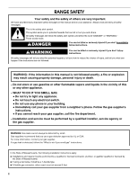
from a neighbor's phone. Follow the gas supplier's instructions. • If you cannot reach your gas supplier, call the fire department. - Installation and service must be performed by a qualified installer, service agency or the gas supplier. WARNING: Gas leaks cannot always be detected by smell - Whirlpool SF216LXSQ | Installation Instructions - Page 3
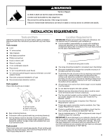
-tip bracket to rear range foot. Reconnect the anti-tip bracket, if the range is moved. Failure to follow these instructions can result in death or serious burns to children and adults. INSTALLATION REQUIREMENTS Tools and Parts Gather the required tools and parts before starting installation. Read - Whirlpool SF216LXSQ | Installation Instructions - Page 4
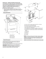
range hood or microwave hood combination above the range, follow the range hood or microwave hood combination installation instructions for installation of electrical outlet. G. This shaded area recommended for installation of rigid gas pipe. H. 2" (5.1 cm) min. countertop space to side wall or other - Whirlpool SF216LXSQ | Installation Instructions - Page 5
the manufacturer's instructions. Type of Gas Natural gas: This range is design-certified by CSA International for use with Natural gas or, after proper conversion, for use with LP gas. ■ This range is factory set for use with Natural gas. See "Gas Conversions" section. The model/serial rating plate - Whirlpool SF216LXSQ | Installation Instructions - Page 6
) or lower The range must be isolated from the gas supply piping system by closing its individual manual shutoff valve during any pressure testing of the gas supply piping system at test pressures equal to or less than ½ psi (3.5 kPa). INSTALLATION INSTRUCTIONS Unpack Range WARNING 5. Using 2 or - Whirlpool SF216LXSQ | Installation Instructions - Page 7
Anti-Tip Bracket WARNING Tip Over Hazard A child or adult can tip the range and be killed. Connect anti-tip bracket to rear range foot. Reconnect the anti-tip bracket, if the range is moved. Failure to follow these instructions can result in death or serious burns to children and adults. Align the - Whirlpool SF216LXSQ | Installation Instructions - Page 8
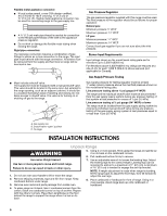
, authorized gas company personnel, and authorized service personnel. Manual shutoff valve H. ½" or ¾" gas pipe Complete Connection 1. Locate gas pressure regulator in the broiler. A Typical rigid pipe connection A combination of pipe fittings must be used to connect the range to the existing gas - Whirlpool SF216LXSQ | Installation Instructions - Page 9
manual shutoff valve in the gas supply line. The valve is open when the handle is parallel to the gas use an extension cord. Failure to follow these instructions can result in death, fire, or electrical adjusting: 1. Turn control knob to the "Lo" setting and remove control knob. 2. Insert a small - Whirlpool SF216LXSQ | Installation Instructions - Page 10
and Care Guide for specific instruction on range operation. If range does not operate, check the following: ■ Household fuse is intact and tight, or circuit breaker has not tripped. ■ Range is plugged into a grounded 3 prong outlet. ■ Electrical supply is connected. ■ See "Troubleshooting" in the - Whirlpool SF216LXSQ | Installation Instructions - Page 11
: Please reference the "Assistance or Service" section of the Use and Care Guide or contact the dealer from whom you purchased your range. GAS CONVERSIONS Gas conversions from Natural gas to LP gas or from LP gas to 2. Unplug range or disconnect power. Natural gas must be done by a qualified - Whirlpool SF216LXSQ | Installation Instructions - Page 12
spud stamped with "56" 6. Place Natural gas oven burner spud in plastic parts bag along with Natural gas cooktop burner spuds for future use and keep the "Make Gas Connection" section for properly connecting the range to the gas supply. 2. Turn the manual shutoff valve in the gas supply line to - Whirlpool SF216LXSQ | Installation Instructions - Page 13
is moved. Failure to follow these instructions can result in death or serious burns to children and adults. 1. Turn manual shutoff valve to the "closed" position. 2. Unplug range or disconnect power. B A C A. To range B. Manual shutoff valve "closed" position C. Gas supply line 4. Reinstall the cap - Whirlpool SF216LXSQ | Installation Instructions - Page 14
range. A. Natural gas oven orifice spud stamped with "47" IMPORTANT: Do not overtighten. 6. Place LP gas oven burner spud in plastic parts bag along with LP gas "Make Gas Connection" section for properly connecting the range to the gas supply. 2. Turn the manual shutoff valve in the gas supply line - Whirlpool SF216LXSQ | Installation Instructions - Page 15
muy importante. Hemos incluido muchos mensajes importantes de seguridad en este manual y en su electrodoméstico. Lea y obedezca siempre todos los u otro aparato electrodoméstico. - PASOS QUE USTED DEBE SEGUIR SI HUELE A GAS: • No trate de encender ningún aparato electrodoméstico. • No toque ningún - Whirlpool SF216LXSQ | Installation Instructions - Page 16
de manigueta T. ■ Si se usa un conector de gas flexible no debe exceder de 3 pies. ADVERTENCIA Peligro de de hoja plana ■ Destornillador Phillips ■ Taladro manual o eléctrico ■ Llave de tuerca o recinto completamente cerrado de los lados y la parte posterior de la estufa. ■ Para eliminar - Whirlpool SF216LXSQ | Installation Instructions - Page 17
mínimo de la abertura del armario D. Para ver el espacio mínimo hasta la parte superior de la superficie de cocción, vea la NOTA*. E. 30¹⁄₈" (76,5 cm G. Se recomienda esta área sombreada para la instalación de la tubería de gas rígida H. 2" (5,1 cm) de espacio mínimo del mostrador a la pared lateral - Whirlpool SF216LXSQ | Installation Instructions - Page 18
está debidamente polarizado. ■ El diagrama de cableado está ubicado en la parte posterior de la estufa, en una bolsa de plástico transparente. NOTA: El Estadounidense (American National Standard), el Código Nacional de Gas Combustible (National Fuel Gas Code), ANSI Z223.1- última edición o CAN/CGA - Whirlpool SF216LXSQ | Installation Instructions - Page 19
ón de una columna de agua de 14") o menor La estufa deberá aislarse del sistema de tubería del suministro de gas cerrando la válvula de cierre individual manual durante toda prueba de presión efectuada en dicho sistema a presiones de prueba iguales o menores de ½ lb/pulg² (3,5 kPa). A C A. Línea - Whirlpool SF216LXSQ | Installation Instructions - Page 20
de cartón debajo de la estufa. 3. Saque las parrillas del horno y el paquete de piezas del interior del horno. 4. Para colocar la estufa sobre su parte posterior, tome los 4 esquinales de cartón de la caja. Apile un esquinal de cartón sobre el otro. Repita con los otros 2 esquinales. Colóquelos a lo - Whirlpool SF216LXSQ | Installation Instructions - Page 21
Si la abertura del armario es más ancha que lo especificado en la sección "Requisitos de ubicación", ajuste la plantilla de manera que la estufa esté centrada en la abertura del armario. 5. Para montar el soporte anti-vuelco al piso de madera, perfore dos orificios de ¹⁄₈" (0,32 cm) en las - Whirlpool SF216LXSQ | Installation Instructions - Page 22
el otro adaptador a la válvula de cierre de gas. Apriete ambos adaptadores. 22 Vista frontal Válvula de cierre Parte frontal Vista lateral Posición "ON" (Abierto) 3. Abra la válvula de cierre manual de la línea de suministro de gas. La válvula está abierta cuando la manija está paralela al tubo - Whirlpool SF216LXSQ | Installation Instructions - Page 23
de pared de conexión a tierra de 3 terminales. Verifique el funcionamiento Sistema de encendido electrónico Encendido inicial y ajustes de la llama de gas Los quemadores de la superficie de cocción y el horno usan encendedores electrónicos en lugar de pilotos permanentes. Cuando se gira la perilla - Whirlpool SF216LXSQ | Installation Instructions - Page 24
horno requiere un tiempo determinado antes de abrirse y dejar que fluya el gas. El quemador del horno funcionará hasta que el mismo haya alcanzado una temperatura la estufa" del Manual de uso y cuidado. 6. Lea el Manual de uso y cuidado. 7. Encienda los quemadores y el horno. Vea el Manual de uso y - Whirlpool SF216LXSQ | Installation Instructions - Page 25
Sírvase consultar la sección "Ayuda o servicio técnico" del Manual de uso y cuidado o póngase en contacto con el distribuidor en donde usted compró la estufa. CONVERSIONES DE GAS Las conversiones de gas natural a gas L.P. o de gas L.P. a gas natural deberán ser hechas por un instalador calificado - Whirlpool SF216LXSQ | Installation Instructions - Page 26
B. Quemador C. Quemador central 2. Ubique las espitas de los orificios de gas L.P. para los quemadores superiores, que están en la bolsa con material de aire del quemador del horno. 3. Ubique la espita del orificio de gas L.P. marcada con "56" en la bolsa con material impreso que se suministr - Whirlpool SF216LXSQ | Installation Instructions - Page 27
de "cerrado". 2. Desenchufe la estufa o desconecte el suministro de energía. B A C A. A la estufa B. Válvula de cierre manual en la posición "cerrada" C. Línea de suministro de gas A A. Tapa 4. Vuelva a colocar la tapa. Cómo convertir los quemadores de superficie 1. Saque la parrilla, las tapas del - Whirlpool SF216LXSQ | Installation Instructions - Page 28
obturador de aire del quemador del horno. 3. Ubique la espita del orificio de gas natural marcada con "47" en la bolsa con material impreso que se suministró de gas" para conectar la estufa debidamente al suministro de gas. 2. Gire la válvula de cierre manual en la línea de suministro de gas a
-
 1
1 -
 2
2 -
 3
3 -
 4
4 -
 5
5 -
 6
6 -
 7
7 -
8
-
9
-
10
-
11
-
12
-
13
-
14
-
15
-
16
-
17
-
18
-
19
-
20
-
21
-
22
-
23
-
24
-
25
-
26
-
27
-
28
 |
 |

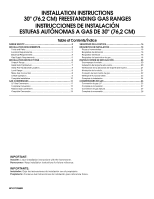
INSTALLATION INSTRUCTIONS
30" (76.2 CM) FREESTANDING GAS RANGES
INSTRUCCIONES DE INSTALACIÓN
ESTUFAS AUTÓNOMAS A GAS DE 30" (76,2 CM)
W10110358B
Table of Contents/Índice
RANGE SAFETY
.......................................................................................
2
INSTALLATION REQUIREMENTS
.........................................................
3
Tools and Parts
.....................................................................................
3
Location Requirements
.........................................................................
3
Electrical Requirements
........................................................................
5
Gas Supply Requirements
....................................................................
5
INSTALLATION INSTRUCTIONS
...........................................................
6
Unpack Range
......................................................................................
6
Install Anti-Tip Bracket
..........................................................................
7
Verify Anti-Tip Bracket Location
...........................................................
8
Level Range
..........................................................................................
8
Make Gas Connection
..........................................................................
8
Check Operation
...................................................................................
9
Complete Installation
..........................................................................
10
GAS CONVERSIONS
.............................................................................
11
LP Gas Conversion
.............................................................................
11
Complete Conversion
.........................................................................
12
Natural Gas Conversion
......................................................................
13
Complete Conversion
.........................................................................
14
SEGURIDAD DE LA ESTUFA
...............................................................
15
REQUISITOS DE INSTALACIÓN
..........................................................
16
Piezas y herramientas
.........................................................................
16
Requisitos de ubicación
.....................................................................
16
Requisitos eléctricos
..........................................................................
18
Requisitos del suministro de gas
.......................................................
18
INSTRUCCIONES DE INSTALACIÓN
..................................................
20
Desempaque la estufa
........................................................................
20
Instalación del soporte anti-vuelco
....................................................
20
Verificación de la ubicación del soporte anti-vuelco
.........................
21
Nivelación de la estufa
........................................................................
21
Conexión del suministro de gas
.........................................................
22
Verifique el funcionamiento
................................................................
23
Complete la instalación
......................................................................
24
CONVERSIONES DE GAS
....................................................................
25
Conversión de gas L.P
. ......................................................................
25
Complete la conversión
......................................................................
27
Conversión de gas natural
..................................................................
27
Complete la conversión
......................................................................
28
IMPORTANT:
Installer:
Leave installation instructions with the homeowner.
Homeowner:
Keep installation instructions for future reference.
IMPORTANTE:
Instalador:
Deje las instrucciones de instalación con el propietario.
Propietario:
Conserve las instrucciones de instalación para referencia futura.