Whirlpool SF216LXSQ Installation Instructions - Page 8
Verify Anti-Tip Bracket Location, Level Range, Make Gas Connection
 |
UPC - 883049035079
View all Whirlpool SF216LXSQ manuals
Add to My Manuals
Save this manual to your list of manuals |
Page 8 highlights
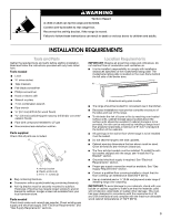
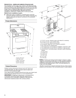
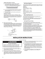
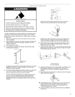
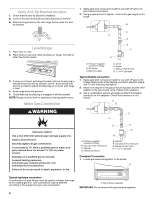
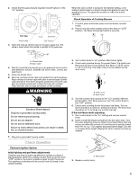
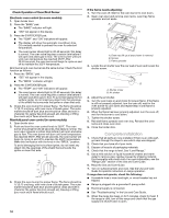
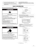
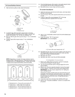
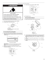
Verify Anti-Tip Bracket Location 1. Check that the anti-tip bracket is installed: ■ Look for the anti-tip bracket securely attached to the floor. ■ Slide the range back so the rear range foot is under the antitip bracket. 1. Apply pipe-joint compound made for use with LP gas to all pipe thread connections. 2. Using a pipe wrench to tighten, connect the gas supply to the range. B Level Range 1. Place rack in oven. 2. Place level on rack and check levelness of range, first side to side; then front to back. C A D E F G 3. If range is not level, pull range forward until rear leveling leg is removed from the anti-tip bracket. Use ³⁄₈" drive ratchet and wrench or pliers to adjust leveling legs up or down until range is level. 4. Push range back into position. 5. Check that rear leveling leg is engaged in anti-tip bracket. NOTE: Range must be level for satisfactory baking performance. Make Gas Connection A. Pressure regulator connection fitting B. 90° elbow C. Black iron pipe D. Union E. Nipple F. Manual shutoff valve G. ½" or ¾" gas pipe Typical flexible connection 1. Apply pipe-joint compound made for use with LP gas to the smaller thread ends of the flexible connector adapters (see B and F in the following illustration). 2. Attach one adapter to the gas pressure regulator and the other adapter to the gas shutoff valve. Tighten both adapters. 3. Use a combination wrench and pliers to attach the flexible connector to the adapters. Check that connector is not kinked. A B WARNING D C Explosion Hazard Use a new CSA International approved gas supply line. Install a shut-off valve. Securely tighten all gas connections. If connected to LP, have a qualified person make sure gas pressure does not exceed 14" (36 cm) water column. Examples of a qualified person include: licensed heating personnel, authorized gas company personnel, and authorized service personnel. Failure to do so can result in death, explosion, or fire. E F G H A. Pressure regulator connection fitting B. Use pipe-joint compound. C. Adapter D. Flexible connector E. Adapter F. Use pipe-joint compound. G. Manual shutoff valve H. ½" or ¾" gas pipe Complete Connection 1. Locate gas pressure regulator in the broiler. A Typical rigid pipe connection A combination of pipe fittings must be used to connect the range to the existing gas line. Your connections may be different, according to the supply line type, size and location. 8 A. Gas pressure regulator IMPORTANT: Do not remove the gas pressure regulator.
-
 1
1 -
2
-
 3
3 -
 4
4 -
 5
5 -
 6
6 -
 7
7 -
 8
8 -
 9
9 -
 10
10 -
 11
11 -
 12
12 -
 13
13 -
14
-
15
-
16
-
17
-
18
-
19
-
20
-
21
-
22
-
23
-
24
-
25
-
26
-
27
-
28
 |
 |
