Whirlpool SF216LXSQ Installation Instructions - Page 9
Check Operation - knob
 |
UPC - 883049035079
View all Whirlpool SF216LXSQ manuals
Add to My Manuals
Save this manual to your list of manuals |
Page 9 highlights
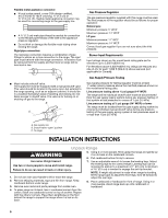
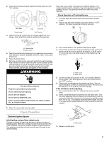
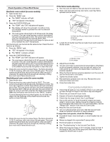
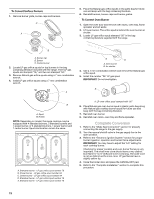
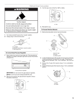
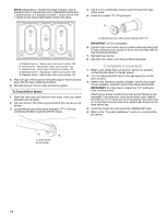
2. Check that the gas pressure regulator shutoff valve is in the "on" position. Front View Front Side View Shutoff valve "ON" Position 3. Open the manual shutoff valve in the gas supply line. The valve is open when the handle is parallel to the gas pipe. A B A. Closed valve B. Open valve 4. Test all connections by brushing on an approved noncorrosive leak-detection solution. Bubbles will show a leak. Correct any leak found. 5. Close the broiler door. 6. Remove cooktop burner caps and grates from parts package. Align notches in burner caps with pins in burner base. Burner caps should be level when properly positioned. If burner caps are not properly positioned, surface burners will not light. Place burners, burner caps and grates on the cooktop. WARNING Electrical Shock Hazard Plug into a grounded 3 prong outlet. Do not remove ground prong. Do not use an adapter. Do not use an extension cord. Failure to follow these instructions can result in death, fire, or electrical shock. When the oven control is turned to the desired setting, a hot surface igniter heats to a bright orange and ignites the gas. No sparking occurs. The glow bar remains on while the burner operates. Check Operation of Cooktop Burners 1. If control panel and knobs were removed earlier, reinstall knobs. 2. Push in and turn each surface unit control knob to "LITE" position. The flame should light within 4 seconds. OFF LITE LO HI MED 3. Turn control knob to "HI" position after burner lights. 4. Check each cooktop burner for proper flame. The small inner flame should have a very distinct blue flame ¼" (0.64 cm) to ½" (0.13 cm) long. The outer cone is not as distinct as the inner cone. A B A. Outer cone B. Inner cone 5. Turn the control knob quickly to the "LO" position after the burner lights. If the flame goes out, turn the control knob to the "OFF" position. 6. Check each cooktop burner for proper low flame. The low flame should be a minimum, steady blue flame. The flame size should be ¼" to ³⁄₈" (0.64 cm to 0.95 cm) high. If the low flame needs adjusting: 1. Turn control knob to the "Lo" setting and remove control knob. 2. Insert a small flat-blade screwdriver into the valve stem. Turn the valve adjusting screw to obtain the smallest flame that will not go out when the control of a cold burner is quickly turned from "HI" to "Lo." Turn right to decrease flame height. Turn left to increase flame height. Repeat for other cooktop burners as needed. 7. Plug into a grounded 3 prong outlet. Check Operation Electronic Ignition System Initial lighting and gas flame adjustments Cooktop and oven burners use electronic igniters in place of standing pilots. When the cooktop control knob is turned to the "LITE" position, the system creates a spark to light the burner. This sparking continues until the control knob is turned to the desired setting. A A. Valve stem 3. Replace control knob. 9
-
 1
1 -
2
-
3
-
 4
4 -
 5
5 -
 6
6 -
 7
7 -
 8
8 -
 9
9 -
 10
10 -
 11
11 -
 12
12 -
 13
13 -
 14
14 -
15
-
16
-
17
-
18
-
19
-
20
-
21
-
22
-
23
-
24
-
25
-
26
-
27
-
28
 |
 |
