Whirlpool WCG52424AS Installation Guide - Page 7
Make Gas Connection
 |
View all Whirlpool WCG52424AS manuals
Add to My Manuals
Save this manual to your list of manuals |
Page 7 highlights
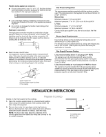
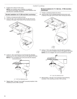
Make Gas Connection WARNING Explosion Hazard Use a new CSA International approved gas supply line. Install a shut-off valve. Securely tighten all gas connections. Typical flexible connection 1. Apply pipe-joint compound made for use with LP gas to the smaller thread ends of the flexible connector adapters (see G in the following illustration). 2. Attach 1 adapter and nipple to the gas pressure regulator and the other adapter and nipple to the gas shutoff valve. Tighten both adapters and nipples. 3. Use a combination wrench and pliers to attach the flexible connector to the adapters. Check that connector is not kinked. B A C D If connected to LP, have a qualified person make sure gas pressure does not exceed 14" (36 cm) water column. Examples of a qualified person include: licensed heating personnel, authorized gas company personnel, and authorized service personnel. Failure to do so can result in death, explosion, or fire. To Assemble Pressure Regulator: 1. Using 2 or more people, stand the cooktop on its side or back. 2. Connect the flexible stainless steel connector to the pressure regulator using a ½" male pipe thread adapter and nipple. A combination of pipe fittings must be used to connect the cooktop to the existing gas line. Shown following is a typical connection. Your connection may be different, according to the supply line type, size and location. 3. Install the pressure regulator with the arrow pointing up toward the bottom of the cooktop base and in a position where you can reach the regulator cap. B H A. ³⁄₈" nipple B. ³⁄₈" adapter C. Flexible connector D. ½" nipple F G E E. Gas pressure regulator F. ½" adapter G. Use pipe-joint compound. H. Manual gas shutoff valve Complete Connection 1. Open the manual shutoff valve in the gas supply line. The valve is open when the handle is parallel to the gas pipe. A B A. Closed valve B. Open valve 2. Test all connections by brushing on an approved noncorrosive leak-detection solution. Bubbles will show a leak. Correct any leak found. 3. Remove surface burner caps and grates from parts package. Align notches in burner caps with pins in burner base. Burner caps should be level when properly positioned. If burner caps are not properly positioned, surface burners will not light. Place burner grates over burners and caps. A C D B A C A. Access cap B. Rear of cooktop C. Gas pressure regulator D. Up arrow. Regulator must be installed with arrow pointing up to cooktop bottom. IMPORTANT: All connections must be wrench-tightened. Do not make connections to the gas regulator too tight. Making the connections too tight may crack the regulator and cause a gas leak. Do not allow the regulator to turn on the pipe when tightening fittings. Use only pipe-joint compound made for use with Natural and LP gas. Do not use TEFLON® tape. You will need to determine the fittings required depending on your installation. A. Igniter electrode B. Burner cap C. Burner base 7
-
 1
1 -
 2
2 -
 3
3 -
 4
4 -
 5
5 -
 6
6 -
 7
7 -
 8
8 -
 9
9 -
 10
10 -
 11
11 -
 12
12 -
13
-
14
-
15
-
16
-
17
-
18
-
19
-
20
 |
 |
