Whirlpool WED7500VW Owners Manual - Page 12
Install Vent System, Connect Vent
 |
UPC - 883049138251
View all Whirlpool WED7500VW manuals
Add to My Manuals
Save this manual to your list of manuals |
Page 12 highlights
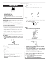
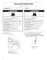
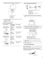
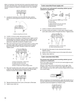
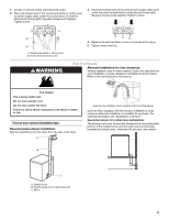
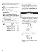
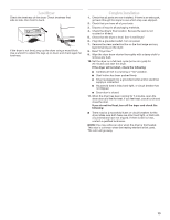
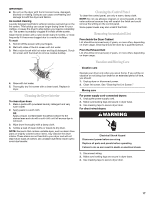
Determine vent path s Select the route that will provide the straightest and most direct path outdoors. s Plan the installation to use the fewest number of elbows and turns. s When using elbows or making turns, allow as much room as possible. s Bend vent gradually to avoid kinking. s Use the fewest 90° turns possible. Determine vent length and elbows needed for best drying performance s Use the following Vent system chart to determine type of vent material and hood combinations acceptable to use. NOTE: Do not use vent runs longer than those specified in the Vent system chart. Exhaust systems longer than those specified will: s Shorten the life of the dryer. s Reduce performance, resulting in longer drying times and increased energy usage. The Vent system chart provides venting requirements that will help to achieve the best drying performance. Vent system chart Number of 90º turns or elbows Type of vent Box or louvered hoods Angled hoods 0 Rigid metal 90 ft (27.4 m) 80 ft (24.4 m) Flexible metal 64 ft (19.5 m) 58 ft (17.7 m) 1 Rigid metal 80 ft (24.4 m) 70 ft (21.3 m) Flexible metal 58 ft (17.7 m) 52 ft (15.8 m) 2 Rigid metal 70 ft (21.3 m) 60 ft (18.3 m) Flexible metal 50 ft (15.2 m) 42 ft (12.8 m) Install Vent System 1. Install exhaust hood. Use caulking compound to seal exterior wall opening around exhaust hood. 2. Connect vent to exhaust hood. Vent must fit inside exhaust hood. Secure vent to exhaust hood with 4" (10.2 cm) clamp. 3. Run vent to dryer location. Use the straightest path possible. See "Determine vent path" in "Plan Vent System." Avoid 90º turns. Use clamps to seal all joints. Do not use duct tape, screws or other fastening devices that extend into the interior of the vent to secure vent. Connect Vent WARNING Excessive Weight Hazard Use two or more people to move and install dryer. Failure to do so can result in back or other injury. 1. To protect the floor, use a large, flat piece of cardboard from the dryer carton. Place cardboard under the entire bottom of the dryer. 2. Slide the dryer on the cardboard until it is close to its final location. Leave enough room to connect the exhaust vent. 3. Using the coupling supplied with the dryer, connect the exhaust vent to the coupling and secure with a 4" (10.2 cm) vent clamp. See illustration below. A B CDE A. Coupling B. Vent clamp C. Vent coupler D. Vent clamp E. Rigid or flexible metal vent If connecting to existing vent, make sure the vent is clean. 4. Turn the coupling and exhaust vent assembly counterclockwise in the exhaust hole on the back of the dryer. 5. Make sure the exhaust vent is placed inside the exhaust hood and then secured to the exhaust hood with a 4" (10.2 cm) vent clamp. 6. Move dryer into its final location. Do not crush or kink vent. 12
-
 1
1 -
2
-
3
-
4
-
5
-
6
-
 7
7 -
 8
8 -
 9
9 -
 10
10 -
 11
11 -
 12
12 -
 13
13 -
 14
14 -
 15
15 -
 16
16 -
 17
17 -
18
-
19
-
20
 |
 |