Whirlpool WFG745H0FS Use & Care Guide - Page 7
cooktop use, Sealed Surface Burners - gas range
 |
View all Whirlpool WFG745H0FS manuals
Add to My Manuals
Save this manual to your list of manuals |
Page 7 highlights
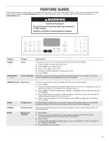
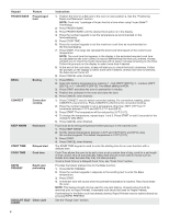
Keypad CONTROL LOCK hold 3 sec to lock SETTINGS Feature Oven control lockout Oven use functions Instructions No keypads will function with the controls locked. 1. Check that the oven and the timer are off. 2. Press and hold the CONTROL LOCK keypad for 3 seconds. 3. If enabled, a tone will sound, and "CONTROL LOCKED" will be displayed. 4. Repeat to unlock. Enables you to personalize the audible tones and oven operation to suit your needs. See the "Oven Use" section." COOKTOP USE WARNING Sealed Surface Burners Fire Hazard Do not let the burner flame extend beyond the edge of the pan. Turn off all controls when not cooking. Failure to follow these instructions can result in death or fire. Electric igniters automatically light the surface burners when control knobs are turned to IGNITE. Before setting a control knob, place filled cookware on the grate. Do not operate a burner using empty cookware or without cookware on the grate. The flame should be adjusted so it does not extend beyond the edge of the pan. To Set: 1. Push in and turn knob counterclockwise to IGNITE. All surface burners will click. Only the burner with the control knob turned to IGNITE will produce a flame. 2. Turn knob to anywhere between HIGH and LOW. REMEMBER: When range is in use, the entire cooktop area may become hot. Power™ Burner Feature The front burner is designed to give maximum power when fully on. It can be used to rapidly bring liquid to a boil and to cook large quantities of food. AccuSimmer® Burner Feature The AccuSimmer® feature allows for more precise simmering and low temperature cooking. It is the right rear burner. Power Failure In case of prolonged power failure, the surface burners can be lit manually. Hold a lit match near a burner, and then turn knob counterclockwise to IGNITE. After burner lights, turn knob to setting. A A B D B D E E C A. Burner cap B. Burner base C. Alignment pins D. Igniter E. Gas tube opening NOTE: The oval burner base is permanently attached to the burner cap. IMPORTANT: Do not obstruct the flow of combustion and ventilation air around the burner grate edges. Burner Cap: Always keep the burner cap in place when using a surface burner. A clean burner cap will help avoid poor ignition and uneven flames. Always clean the burner cap after a spillover and routinely remove and clean the caps according to the "General Cleaning" section. Gas Tube Opening: Gas must flow freely throughout the gas tube opening for the burner to light properly. Keep this area free of soil and do not allow spills, food, cleaning agents, or any other material to enter the gas tube opening. Keep spillovers out of the gas tube opening by always using a burner cap. A B A. 1" to 11/2" (2.5 cm to 3.8 cm) B. Burner ports Burner Ports: Check burner flames occasionally for proper size and shape as shown in the previous illustration. A good flame is blue in color, not yellow. Keep this area free of soil and do not allow spills, food, cleaning agents, or any other material to enter the burner ports. 7
-
 1
1 -
 2
2 -
 3
3 -
 4
4 -
 5
5 -
 6
6 -
 7
7 -
 8
8 -
 9
9 -
 10
10 -
 11
11 -
 12
12 -
13
-
14
-
15
-
16
-
17
-
18
-
19
-
20
-
21
-
22
-
23
-
24
-
25
-
26
-
27
-
28
-
29
-
30
-
31
-
32
-
33
-
34
-
35
-
36
-
37
-
38
-
39
-
40
-
41
-
42
-
43
-
44
 |
 |
