Whirlpool WGG755S0BS Installation Guide - Page 8
Install Anti-Tip Bracket, Make Gas Connection
 |
View all Whirlpool WGG755S0BS manuals
Add to My Manuals
Save this manual to your list of manuals |
Page 8 highlights
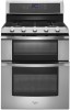
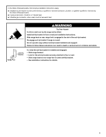
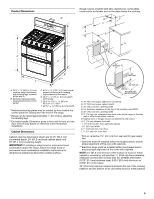
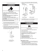
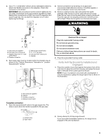
Install Anti-Tip Bracket WARNING 4. Drill two ¹⁄₈" (3.0 mm) holes that correspond to the bracket holes of the determined mounting method. See the following illustrations. Floor Mounting Wall Mounting A B A B Tip Over Hazard A child or adult can tip the range and be killed. Install anti-tip bracket to floor or wall per installation instructions. Slide range back so rear range foot is engaged in the slot of the anti-tip bracket. Re-engage anti-tip bracket if range is moved. Do not operate range without anti-tip bracket installed and engaged. Failure to follow these instructions can result in death or serious burns to children and adults. 1. Remove the anti-tip bracket that is taped inside the upper oven with the package containing literature. 2. Determine which mounting method to use: floor or wall. If you have a stone or masonry floor, you can use the wall mounting method. 3. Determine and mark edge of range in the cutout space. The mounting bracket can be installed on either the left side or right side of the cutout. Position mounting bracket in cutout so that right (or left) edge of the bracket is 2.4 cm) from the marked edge of the range, as shown. A B C A. Anti-tip bracket B. Mark edge of range. C 2.4 cm) A. #12 x 1⁵⁄₈" screws B. Anti-tip bracket A. #12 x 1⁵⁄₈" screws B. Anti-tip bracket 5. Using a Phillips screwdriver, mount anti-tip bracket to the wall or floor with the two #12 x 1⁵⁄₈" screws provided. Make Gas Connection WARNING Explosion Hazard Use a new CSA International approved gas supply line. Install a shut-off valve. Securely tighten all gas connections. If connected to LP, have a qualified person make sure gas pressure does not exceed 14" (36 cm) water column. Examples of a qualified person include: licensed heating personnel, authorized gas company personnel, and authorized service personnel. Failure to do so can result in death, explosion, or fire. Typical flexible connection 1. Apply pipe-joint compound made for use with LP gas to the smaller thread ends of the flexible connector adapters (see B and G in the following illustration). 2. Attach one adapter to the gas pressure regulator and the other adapter to the gas shutoff valve. Tighten both adapters, being certain not to move or turn the gas pressure regulator. 8
-
 1
1 -
2
-
 3
3 -
 4
4 -
 5
5 -
 6
6 -
 7
7 -
 8
8 -
 9
9 -
 10
10 -
 11
11 -
 12
12 -
 13
13 -
14
-
15
-
16
-
17
-
18
-
19
-
20
-
21
-
22
-
23
-
24
-
25
-
26
-
27
-
28
-
29
-
30
-
31
-
32
-
33
-
34
-
35
-
36
-
37
-
38
-
39
-
40
 |
 |