Whirlpool WGG755S0BS Installation Guide - Page 9
Verify Anti-Tip Bracket Is Installed and, Engaged
 |
View all Whirlpool WGG755S0BS manuals
Add to My Manuals
Save this manual to your list of manuals |
Page 9 highlights
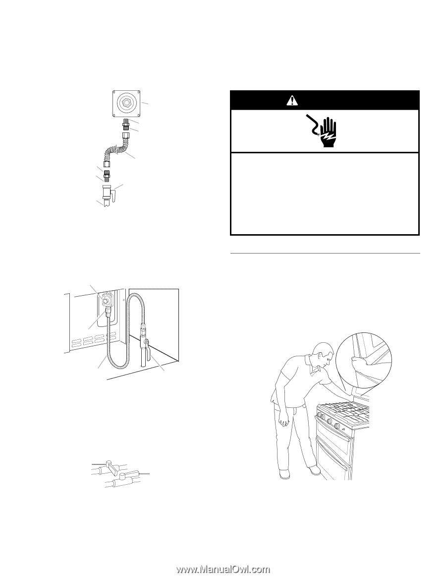
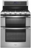
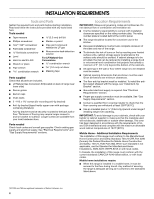
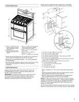
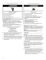
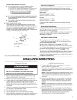
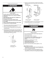
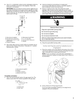
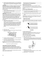
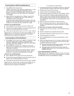
3. Use a combination wrench and an adjustable wrench to attach the flexible connector to the adapters. Check that connector is not kinked. IMPORTANT: All connections must be wrench-tightened. Do not make connections to the gas pressure regulator too tight. Making the connections too tight may crack the regulator and cause a gas leak. Do not allow the regulator to turn when tightening the fittings. A 2. Test all connections by brushing on an approved noncorrosive leak-detection solution. If bubbles appear, a leak is indicated. Correct any leak found. 3. Remove cooktop burner caps and grates from parts package. Align recess in burner caps with pins in burner base. Burner caps should be level when properly positioned. If burner caps are not properly positioned, surface burners will not light. Place burner grates over burners and caps. WARNING B C D H G E F A. Gas pressure regulator B. Use pipe-joint compound. C. Adapter (must have ½" male pipe thread) D. Flexible connector E. Manual gas shutoff valve F. ½" or ¾" gas pipe G. Use pipe-joint compound. H. Adapter 4. Gas supply pipe must be located within the shaded area as shown in the "Cabinet Dimensions" illustration in "Location Requirements" section. A Adaptor B Electrical Shock Hazard Plug into a grounded 3 prong outlet. Do not remove ground prong. Do not use an adapter. Do not use an extension cord. Failure to follow these instructions can result in death, fire, or electrical shock. 4. Plug into a grounded 3 prong outlet. Verify Anti-Tip Bracket Is Installed and Engaged 1. Place the outside of your foot against the bottom front of the oven door to keep the unit from moving, and grasp the lower right or left side of the control panel as shown. NOTE: If your countertop is mounted with a backsplash, it may be necessary to grasp the range higher than is shown in the illustration. C D A. Gas pressure regulator B. Adapter C. Flexible connector D. Manual shutoff valve Complete connection 1. Open the manual shutoff valve in the gas supply line. The valve is open when the handle is parallel to the gas pipe. A B A. Closed valve B. Open valve 2. Slowly attempt to tilt the range forward. If you encounter immediate resistance, the range foot is engaged in the anti-tip bracket. 9
-
 1
1 -
2
-
3
-
 4
4 -
 5
5 -
 6
6 -
 7
7 -
 8
8 -
 9
9 -
 10
10 -
 11
11 -
 12
12 -
 13
13 -
 14
14 -
15
-
16
-
17
-
18
-
19
-
20
-
21
-
22
-
23
-
24
-
25
-
26
-
27
-
28
-
29
-
30
-
31
-
32
-
33
-
34
-
35
-
36
-
37
-
38
-
39
-
40
 |
 |