Xerox 7700DX Service Manual
Xerox 7700DX - Phaser Color Laser Printer Manual
 |
View all Xerox 7700DX manuals
Add to My Manuals
Save this manual to your list of manuals |
Xerox 7700DX manual content summary:
- Xerox 7700DX | Service Manual - Page 1
Service Manual 701P28180 Phaser® 7700 Color Laser Printer - Xerox 7700DX | Service Manual - Page 2
- Xerox 7700DX | Service Manual - Page 3
Manual 701P28180 Phaser®7700 Color Laser Printer Warning The following servicing instructions are for use by qualified service personnel only. To avoid personal injury, do not perform any servicing other than that contained in operating instructions unless you are qualified to do so. This printing - Xerox 7700DX | Service Manual - Page 4
and service manuals are intended for use by authorized Xerox service technicians and service partners only and are not for resale. These materials may not be distributed, copied, or otherwise reproduced without prior written consent from Xerox Corporation. XEROX®, CentreWare®, Phaser®, PrintingScout - Xerox 7700DX | Service Manual - Page 5
User Safety Summary Terms in Manual Various terms are used throughout this manual to either provide additional information on a specific topic or to warn of possible area. DANGER: A personal injury hazard exists in the area where you see the sign. Phaser 7700 Color Printer Service Manual iii - Xerox 7700DX | Service Manual - Page 6
component unless you are instructed to do so by a service procedure. Mechanical Components Manually rotate drive assemblies to inspect and gears. Do not try to manually rotate or manually stop the drive assemblies while any printer motor is running iv Phaser 7700 Color Printer Service Manual - Xerox 7700DX | Service Manual - Page 7
labels. WARNING: Turning the power Off using the On/Off switch does not de-energize the printer. You must remove the power cord to disconnect the printer from the main power source. Keep the power cord accessible for removal in case of an emergency. Phaser 7700 Color Printer Service Manual v - Xerox 7700DX | Service Manual - Page 8
needs servicing or repair, ■ And whenever you clean the product. Ground the Product Plug the three-wire power cord (with grounding prong) into grounded AC outlets only. If necessary, contact a licensed electrician to install a properly grounded outlet. vi Phaser 7700 Color Printer Service Manual - Xerox 7700DX | Service Manual - Page 9
the laser. Laser (FDA): Any laser label visible to service must be reproduced in the service manual with location shown or indicated. Safe working procedures and clear warnings concerning precautions to avoid possible exposure must also be included. Phaser 7700 Color Printer Service Manual vii - Xerox 7700DX | Service Manual - Page 10
interference, refer to the Federal Communications Commission's booklet "How to Identify and Resolve Radio-TV Interference Problems." This booklet is available from the U.S. Government Printing Office, Washington D.C. 20402, Stock No. 004-000-00345-4. viii Phaser 7700 Color Printer Service Manual - Xerox 7700DX | Service Manual - Page 11
est conforme aux limites émission de bruits radioélectriques pour les appareils de classe B stipulés das le réglement sur le brouillage radioéletrique du Ministére des Communcations du Canada der Serie auf Einhaltung der Bestimmungen eingeräumt. Phaser 7700 Color Printer Service Manual ix - Xerox 7700DX | Service Manual - Page 12
floor can generate enough static electricity to damage an ESD. ■ Handle ICs and EPROMs carefully to avoid bending a pin. ■ Pay attention to the direction of parts when mounting or inserting them on a PCB. x Phaser 7700 Color Printer Service Manual - Xerox 7700DX | Service Manual - Page 13
Compliance 1-viii Canadian Notice 1-ix Avis Canadien 1-ix European Notice 1-ix Hinweis ...1-ix ESD Precautions ...1-x Contents 2-xi List of Tables 2-xxi List of Figures 1-xxiii Phaser 7700 Color Laser Printer Service Manual xi - Xerox 7700DX | Service Manual - Page 14
Printer Specifications 1-24 Physical Dimensions and Clearances 1-24 Supported Paper Weights, Page Sizes and Print Area 1-27 Diagnostics, Error Codes and Messages 2-31 Error Messages 2-31 Troubleshooting Error Codes 34 Service Diagnostics 2-35 xii Phaser 7700 Color Laser Printer Service Manual - Xerox 7700DX | Service Manual - Page 15
3-97 Checking the Toner Cartridge 3-97 Checking the Toner Auger System 3-98 Checking the Developer ATC Sensor 3-101 Checking the Developer 3-102 Tips ...3-102 Operation System and Application Problems 3-104 Macintosh Printing Problems 3-104 Phaser 7700 Color Laser Printer Service Manual xiii - Xerox 7700DX | Service Manual - Page 16
Adjustment 4-125 Center Skew Adjustment 4-126 Processes of the RegiCon Adjustment 4-127 Check Print-quality 4-127 Preparation for RegiCon 4-127 Registration Control Procedures 4-130 RegiCon Flowchart 4-133 Step 1: Belt Edge Learn 4-134 xiv Phaser 7700 Color Laser Printer Service Manual - Xerox 7700DX | Service Manual - Page 17
Cleaner Assembly Life 6-148 Resetting Transfer Roller Life 6-148 Service Diagnostics NVRAM Resets 6-149 PostScript NVRAM Reset 6-149 Clear Tech Rep Faults 6-149 Reset CRU Life Counters 6-149 Reset Engine NVRAM 6-150 Store Engine NVRAM 6-150 Phaser 7700 Color Laser Printer Service Manual xv - Xerox 7700DX | Service Manual - Page 18
Cartridge Sensor Holder 7-178 Print Cartridge Plate Cover 7-179 Dispense Assembly 7-180 Print Cartridge Plate Assembly 7-182 Developer Housing Assembly 7-185 New Developer 7-204 Engine Control Board 7-206 Engine Control Interface Board 7-207 xvi Phaser 7700 Color Laser Printer Service Manual - Xerox 7700DX | Service Manual - Page 19
Accumulator Belt Drive Assembly 7-217 Developer Drive Assembly 7-218 Print Cartridge Drive Assembly 7-219 Tray 1 Assembly, Left-Hand and Right-Hand Gear (HCF 7-233 FRU Parts List 8-235 PL 8-1 Accumulator Belt FRUs 8-236 PL 8-2 Left 267 Phaser 7700 Color Laser Printer Service Manual xvii - Xerox 7700DX | Service Manual - Page 20
281 Kits ...8-282 Manual Packs & Service Manual 8-283 Software ...8-284 Supplies and Accessories 8-284 Recommended Service Tools 8-285 Test Prints 9-287 Analyzing the Test Print 9-288 Print Color Test Prints 9-289 Diagnostics Mode 9-291 Wiring Diagrams 10-295 Phaser 7700 Finisher 11-313 - Xerox 7700DX | Service Manual - Page 21
Transport Motor (Motor Assembly Main 11-340 Cam Bracket Assembly 11-341 Staple Unit Assembly and Motor 11-342 Compiler Tray 11-344 Finisher FRU Parts List 11-345 Finisher Wiring Diagrams 12-371 Phaser 7700 Color Laser Printer Service Manual xix - Xerox 7700DX | Service Manual - Page 22
xx Phaser 7700 Color Laser Printer Service Manual - Xerox 7700DX | Service Manual - Page 23
1-11 Print Area 1-28 Table 2-1 POST Diagnostics Test Descriptions 2-34 Table 2-2 Service Diagnostics Test Supplies FRUs List (cont'd 8-254 Table 8-13 Motors / Drivers FRUs List 8-256 Table 8-14 Electrophotographic Components FRUs List 8- 279 Phaser 7700 Color Laser Printer Service Manual xxi - Xerox 7700DX | Service Manual - Page 24
8-29 High-Capacity Feeder FRUs (cont'd 8-281 Table 8-30 Kits ...8-282 Table 8-31 Manual Packs & Service Manual 8-283 Table 8-32 Software 8-284 Table 8-33 Supplies 8-284 Table 8-34 Accessories 8-285 Table 11-15 Electrical FRUs List 11-370 xxii Phaser 7700 Color Laser Printer Service Manual - Xerox 7700DX | Service Manual - Page 25
Phaser 7700 Color Laser Printer (shown with the High-Capacity Feeder) 1-1 Figure 1-2 Engine Control Interface and Power Supply Boards 1-6 Figure 1-3 Power Supplies 1-7 Figure 1-4 Engine Control and Image Processor Boards 1-8 Figure 1-5 Auxiliary Feeder Control Board 1-9 Figure 1-6 Print Engine - Xerox 7700DX | Service Manual - Page 26
7-202 Figure 7-46 Internal Hard Drive 7-203 Figure 7-47 Electrical Chassis Assembly 7-204 Figure 7-48 Engine Control Board 7-206 Figure 7-49 Engine Control Interface Board 7-207 Figure 7-50 T1 and T3 High-voltage Power Supplies 7-208 xxiv Phaser 7700 Color Laser Printer Service Manual - Xerox 7700DX | Service Manual - Page 27
Drive Assembly 7-217 Figure 7-58 Developer Drive Assembly 7-218 Figure 7-59 Print Cartridge Drive Assembly 7-219 Figure 7-60 Supplies FRUs (cont'd 8-253 Figure 8-13 Motors/Drivers FRUs 8-255 Figure 8-14 Electrophotographic Components FRUs Phaser 7700 Color Laser Printer Service Manual xxv - Xerox 7700DX | Service Manual - Page 28
FRUs (cont'd 8-280 Figure 8-29 High-Capacity Feeder FRUs (cont'd 8-281 Figure 11-1 Phaser 7700 Color Laser Printer with the Finisher Option 11-313 Figure 11-2 Dimensions of the Finisher 11-315 Figure 11 Figure 11-38 Exit Assembly FRUs 11-368 xxvi Phaser 7700 Color Laser Printer Service Manual - Xerox 7700DX | Service Manual - Page 29
Figure 11-39 Electrical FRUs 11-370 Figure 12-1 Block diagram of the Finisher 12-372 Figure 12-2 Wiring diagram of the Finisher 12-373 Phaser 7700 Color Laser Printer Service Manual xxvii - Xerox 7700DX | Service Manual - Page 30
xxviii Phaser 7700 Color Laser Printer Service Manual - Xerox 7700DX | Service Manual - Page 31
the Xerox Phaser 7700 Color Laser Printer. Certification for servicing of this product requires completion of the Phaser 7700 printer service training. S7700-433 Figure 1-1 The Phaser 7700 Color Laser Printer (shown with the High-Capacity Feeder) Phaser 7700 Color Laser Printer Service Manual 1-1 - Xerox 7700DX | Service Manual - Page 32
Phaser 7700 Printer Overview The Phaser 7700 Color Printer combines a single-pass, tandem-design, color laser, continuous-tone print engine with an image processor supporting Adobe's PostScript 3 description language. The image processor features a bi-directional parallel interface, a USB port, and - Xerox 7700DX | Service Manual - Page 33
after printing, it is stored on the hard drive for print on demand. This function requires the internal hard drive. Note For additional service information, refer to the Service CD-ROM or the Xerox Service Website: http://cpidserv.opbu.xerox.com. Phaser 7700 Color Laser Printer Service Manual - Xerox 7700DX | Service Manual - Page 34
volt ■ 100 MHz PC100 or 133 MHz PC133 The Startup Page and the Configuration Page list the amount of RAM installed in the printer. If for printing one image while processing a second image (which gives greater printing throughput). The printer features Phaser 7700 Color Laser Printer Service Manual - Xerox 7700DX | Service Manual - Page 35
12k at 5% coverage 5k at 5% coverage 10k at 5% coverage 4k at 5% coverage 100k, less w/duplex printing 60K Letter/A4 pgs, 24 lb. paper 300K Accumulator Belt Cleaner Waste Toner Cartridge 24 Months 24 Months 100k 6k, less with media pick jams Phaser 7700 Color Laser Printer Service Manual 1-5 - Xerox 7700DX | Service Manual - Page 36
Supply/ T1 Board High Voltage Power Supply/ T3 Board High Voltage Power Supply/ T2 Board GFI AC Drive Board Noise Filter Board S7700-317 Figure 1-2 Engine Control Interface and Power Supply Boards 1-6 Phaser 7700 Color Laser Printer Service Manual - Xerox 7700DX | Service Manual - Page 37
Power Supplies 24 V Low voltage power supply 24 V Low voltage power supply fan AC Power Chassis 3.3 V Low voltage power supply 5 V Low voltage power supply Figure 1-3 Power Supplies S7700-261 Phaser 7700 Color Laser Printer Service Manual 1-7 - Xerox 7700DX | Service Manual - Page 38
Engine Control and Image Processor Boards Image Processor Board Engine Control Board S7700-381 Figure 1-4 Engine Control and Image Processor Boards 1-8 Phaser 7700 Color Laser Printer Service Manual - Xerox 7700DX | Service Manual - Page 39
Auxiliary Feeder Control Board LTD Board (3T) HCF Board (TT) Figure 1-5 Auxiliary Feeder Control Board S7700-385 Phaser 7700 Color Laser Printer Service Manual 1-9 - Xerox 7700DX | Service Manual - Page 40
Transparency Sensor Registration Sensor Paper On Belt Sensor MPT No Paper Sensor Tray 1 No Paper Sensor/Level Sensor MPT Paper Size Sensor S7700-287 Figure 1-6 Print Engine Sensors and Switches 1-10 Phaser 7700 Color Laser Printer Service Manual - Xerox 7700DX | Service Manual - Page 41
Sensor Duplex Wait Sensor Accumulator Belt Home Sensor Automatic Toner Correction Sensor K, C, M, Y Mark On Belt Sensor Waste Cartridge Full Sensor Tray 1 Paper Size Sensor S7700-288 Figure 1-7 Print Engine Sensors and Switches (cont'd.) Phaser 7700 Color Laser Printer Service Manual 1-11 - Xerox 7700DX | Service Manual - Page 42
-Size Switch Assembly Tray 3 -Tray 3 Tray 4 -Tray 4 HCF 3 Tray 3 Take-Away Sensor Tray 4 Take-Away Sensor Figure 1-8 Auxiliary Feeder Sensors and Switches 2 4 S7700-316 1-12 Phaser 7700 Color Laser Printer Service Manual - Xerox 7700DX | Service Manual - Page 43
tray 4 Paper detect sensor actuator tray 4 Friction clutch tray 3 Paper size switch actuator tray 3 Friction clutch tray 4 S7700-388 Figure 1-9 Auxiliary Feeder Actuators and Clutches Phaser 7700 Color Laser Printer Service Manual 1-13 - Xerox 7700DX | Service Manual - Page 44
clutch Friction clutch One way clutch Exit tray full sensor actuator Paper detect sensor actuator (tray 1) Paper detect sensor actuator (MPT) S7700-387 Figure 1-10 Print Engine Solenoids, Actuators, and Clutches 1-14 Phaser 7700 Color Laser Printer Service Manual - Xerox 7700DX | Service Manual - Page 45
Left hand lower cover sensor Transfer-rollerposition sensor (behind transfer roller) Waste-cartridgeinterlock switch Auxiliaryfeederleft-hand cover-interlock switch S7700-390 Figure 1-11 Print Engine and Auxiliary Feeder Interlocks and Sensors Phaser 7700 Color Laser Printer Service Manual 1-15 - Xerox 7700DX | Service Manual - Page 46
Image Processor Board SODIMM2 SODIMM1 J500 Processor Health LED Hard Drive Ethernet USB DIP Switches NVRAM (socketed) Parallel S7700-258 Figure 1-12 Image Processor Board 1-16 Phaser 7700 Color Laser Printer Service Manual - Xerox 7700DX | Service Manual - Page 47
Assemblies of the Print Engine Fuser assembly Detack Saw connector Paper feeder assembly Left-Hand lower cover assembly Figure 1-13 Assemblies of the Print Engine S7700-266 Phaser 7700 Color Laser Printer Service Manual 1-17 - Xerox 7700DX | Service Manual - Page 48
Assemblies of the Print Engine (cont'd.) Toner cartridge (4x) K C M Y Print cartridge plate Waste cartridge sensor holder Dispenser assembly (4x) Developer housing assemblies (4x) S7700-312 Figure 1-14 Assemblies of the Print Engine (cont'd.) 1-18 Phaser 7700 Color Laser Printer Service Manual - Xerox 7700DX | Service Manual - Page 49
Assemblies of the Print Engine (cont'd.) Exit transport assembly Figure 1-15 Assemblies of the Print Engine (cont'd.) S7700-386 Phaser 7700 Color Laser Printer Service Manual 1-19 - Xerox 7700DX | Service Manual - Page 50
The High-Capacity Feeder has a Tandem Tray design with three Paper Feeder Assemblies, two on the left and one on the right side of the Printer. 1-20 Phaser 7700 Color Laser Printer Service Manual - Xerox 7700DX | Service Manual - Page 51
for the printer. LED indicators ■ Green = Ready to print/printing ■ Flashing Green = Receiving or Processing Data ■ Yellow = Warning ■ Red = Fatal Error Phaser 7700 35 OK ) Button 8 Information Button - for additional explanation or help Phaser 7700 Color Laser Printer Service Manual 1-21 - Xerox 7700DX | Service Manual - Page 52
. Table 1-3 Front Panel Shortcuts Mode Skip execution of POST diagnostics Press this selection at Power On OK Print service diagnostics map Reset PostScript NVRAM INFO BACK+OK Password Bypass Enter Service Diagnostics UP+DOWN BACK+INFO 1-22 Phaser 7700 Color Laser Printer Service Manual - Xerox 7700DX | Service Manual - Page 53
(engineering use only) DOWN UP DOWN Development mode (engineering DOWN use only DOWN DOWN* * Recommended DIP switch position ** If DIP switch 4 is left in the down position, the printer will not turn Off. Switch 4 UP UP DOWN then UP** UP UP Phaser 7700 Color Laser Printer Service Manual - Xerox 7700DX | Service Manual - Page 54
Table 1-5 Physical Dimensions of the Printer Dimension Height Width Depth Weight Value 493 mm (19.4 in.) Print Engine 857 mm (48. in.) (63.1 in.) Figure 1-19 Printer Clearances 5.0 cm (1.96 in.) 42.5 cm (16.7 in.) 106.1 cm (41.8 in.) S7700-417 1-24 Phaser 7700 Color Laser Printer Service Manual - Xerox 7700DX | Service Manual - Page 55
Specification 115/127 VAC 10A (+/- 10%) 200/240 VAC 5A (+/- 10%) 100-127 VAC, 50/60 Hz 220-240 VAC, 50/60 Hz Energy Star: 45 watts Standby: 130 watts Ready: 220 watts Continuous Printing: 220 to 600 watts average Peak (warming up) to 1100 watts Phaser 7700 Color Laser Printer Service Manual 1-25 - Xerox 7700DX | Service Manual - Page 56
Humidly: Operating Storage Altitude Acoustic Noise Idle: Printing: Specification 10 to 32o C -20 to 50o C 10 to 85% relative humidity 30 to 85% relative humidity 0 to 2500 m (8000 ft.) at 25o C 38.3 db 54.8 db with impulse noise of 63.3 db 1-26 Phaser 7700 Color Laser Printer Service Manual - Xerox 7700DX | Service Manual - Page 57
Print Area Supported with the following weights: 170-220 g/m2 (65-80 lb. cover, 100-110 lb. Index). Paper Size Statement (5.5 x 8.5 in.) Executive (7.25 • a. Thin Cover/Index paper cannot be used in Trays 2-4. High-capa city Trays (3-4) • • • Phaser 7700 Color Laser Printer Service Manual 1-27 - Xerox 7700DX | Service Manual - Page 58
Tray 1 Phaser 7700 Premium • Transparency Labels Paper Envelopes (all sizes) Trays 2- 4 MultiPurpose Tray • HighCapacity Feeder • • Table 1-11 Print Area 5 mm .2 in. 5 mm 5 mm .2 in. 5 mm .2 in. 5 mm .2 in. 5 mm 5 mm 5 mm 5 mm 5 mm 1-28 Phaser 7700 Color Laser Printer Service Manual - Xerox 7700DX | Service Manual - Page 59
303 x 432 mm 3.73 x 9.1 in. 95 x 231 mm 8.6 x 11.6 in. 100 x 210 mm 115 x 166 mm 166 x 240 mm 240 x 343 mm 104 x 152 imageable area are supported through the Multi-Purpose Tray (MPT). print-quality outside the imageable area is not guaranteed. Phaser 7700 Color Laser Printer Service Manual 1-29 - Xerox 7700DX | Service Manual - Page 60
1-30 Phaser 7700 Color Laser Printer Service Manual - Xerox 7700DX | Service Manual - Page 61
power On to see if the error recurs. ■ For Printer Performance problems, see Troubleshooting on page 3-87. ■ For Print Image Quality problems, see Print Image Quality Problems on page 3-108. Troubleshooting Error Codes Chain / Link Definitions: A chain-link number is always represented as a pair - Xerox 7700DX | Service Manual - Page 62
processing software. If Post detected any soft errors a message is printed in a red box on the start page. If POST detects any hard errors both the front panel and health Led blink the error code pattern, see LED Blink Patterns on page 2-33. 2-32 Phaser 7700 Color Laser Printer Service Manual - Xerox 7700DX | Service Manual - Page 63
tool for troubleshooting. These POST printed on the StartPage (when the DIP switches are in Customer Mode), see You can print a service Diagnostics menu map by highlighting "Print Service , short, this is fault code 5+5+1+1=12. The exception to the Phaser 7700 Color Laser Printer Service Manual 2-33 - Xerox 7700DX | Service Manual - Page 64
memory. EEPROM 10 (Hard) Addressing of the EEPROM part is tested. Ethernet 11 (Hard) Checks the code indicates 12, you must check the front panel to see if the test name is "CPU Interrupts" or "IDE Disk" before beginning troubleshooting. 2-34 Phaser 7700 Color Laser Printer Service Manual - Xerox 7700DX | Service Manual - Page 65
problem with RegiCon when the customer has the PostScript startpage enabled. Note The Service Menu functions are to be used only by Xerox service personnel and authorized service providers. The printer remove the text and restore the menu. Phaser 7700 Color Laser Printer Service Manual 2-35 - Xerox 7700DX | Service Manual - Page 66
of Jam Built-In Test Prints Prints pre-defined images stored in the engine firmware for troubleshooting image quality problems. Paper Path Options For Print Laser Check only: Selects tray setting? Yes No Press Up/Down to change setting. 2-36 Phaser 7700 Color Laser Printer Service Manual - Xerox 7700DX | Service Manual - Page 67
colors, including developer and toner. All four primaries are present on the page. The print should appear grey. Print Halftones HalfTones Init Startup | Imaging | Delivering | Finishing HalfTones Done Prints 6 pages of 100 C Back Temp is XXo C Phaser 7700 Color Laser Printer Service Manual 2-37 - Xerox 7700DX | Service Manual - Page 68
= Paper present L = Paper not present Engineering use only Engineering use only Engineering use only Engineering use only Engineering use only Engineering use only Engineering use only This is the FIN IN GATE. change when installing a new fuser. 2-38 Phaser 7700 Color Laser Printer Service Manual - Xerox 7700DX | Service Manual - Page 69
No HCF Attached or HCF Path 1 is L HCF Path 2 is| L ATC 1 is nnn ATC 2 is nnn ATC 3 is nnn ATC 4 is nnn High-Capacity Feeder Engineering use only ATC = Automatic Toner Calibration Value range (0 - 1000) Engineering use only Phaser 7700 Color Laser Printer Service Manual 2-39 - Xerox 7700DX | Service Manual - Page 70
Definition Print Cartridge Sensors Print Cart. Yellow is H Print Cart. Magenta is H Print Cart. Cyan is H Print Cart. Black is H H = Cartridge present L = No cartridge present Engineering use unless you perform the 2nd BTR retract motor test. 2-40 Phaser 7700 Color Laser Printer Service Manual - Xerox 7700DX | Service Manual - Page 71
Service Diagnostics Test Menu Functions (cont'd.) Test Front Panel Display Steering Motor Print Cartridge Motor To avoid damaging the Accumulator Belt, remove! Do you wish to continue? Yes No Motor On Motor Off Please cycle power to the printer Phaser 7700 Color Laser Printer Service Manual 2-41 - Xerox 7700DX | Service Manual - Page 72
once per power cycle to avoid excessive toner forced inside the developer and destroying it. Agitator Motor Fuser Fan Motor On Motor setting. Paper Path/No Pick NoPaperRun Init Runs a complete print cycle only no paper is picked and no toner is Phaser 7700 Color Laser Printer Service Manual - Xerox 7700DX | Service Manual - Page 73
On Solenoid Off Engineering use only Engineering use only Press printer. For details on performing the RegiCon procedures, Registration Control Procedures on page 4-130 Belt Edge Learn Refer to (Processes of the RegiCon Adjustment on page 4-127). Phaser 7700 Color Laser Printer Service Manual - Xerox 7700DX | Service Manual - Page 74
Result = 0 Stop Status = 0 ADC Sensor Fail = 0 ADC shutter Fail - 0 Engineering use only This tests the Automatic Density Correction sensor. The highlighted line indicates test results. Tone 3 Rollers Clean Tray 4 Rollers Clean MPT Tray Rollers 2-44 Phaser 7700 Color Laser Printer Service Manual - Xerox 7700DX | Service Manual - Page 75
to Eng NVM from Hard Drive** Are you sure? Yes No Refer to Reset Engine NVRAM on page 6-150. **Writes data to Hard Drive from Eng NVM** Are you sure? Yes No Refer to Store Engine NVRAM on page 6-150. Exits to PostScript without running POST. Phaser 7700 Color Laser Printer Service Manual 2-45 - Xerox 7700DX | Service Manual - Page 76
Codes and Messages Troubleshooting Some Error Codes create "Tech Rep Faults" which must be cleared, see Clear Tech Rep Faults on page 6-149. Voltage Measurements Many voltage measurements are required for expeditious troubleshooting Locations 2-46 Phaser 7700 Color Laser Printer Service Manual - Xerox 7700DX | Service Manual - Page 77
Fuser Connector Pin Locations 1 4 7 10 2 5 8 11 3 6 9 12 Fig 2-2 Fuser Connector Pin Locations S7700-427 Phaser 7700 Color Laser Printer Service Manual 2-47 - Xerox 7700DX | Service Manual - Page 78
Code Chain / Link Front Panel Message 10 06-380 ERROR 10 LASER UNIT FAILURE 06-381 06-382 06-383 06-385 Warning Do not operate the Laser Unit outside the printer problem persists, replace the Engine Control Board (RRP 42, on page 7-206). 2-48 Phaser 7700 Color Laser Printer Service Manual - Xerox 7700DX | Service Manual - Page 79
. Replace the Developer Housing Assembly (RRP 27, on page 7-185). Replace the Engine Control Board (RRP 42, on page 7-206). Note Run approximately 10 pages of solid fill full-page prints of this primary color to ensure this error is cleared. Phaser 7700 Color Laser Printer Service Manual 2-49 - Xerox 7700DX | Service Manual - Page 80
. Replace the Developer Housing Assembly (RRP 27, on page 7-185). Replace the Engine Control Board (RRP 42, on page 7-206). Note Run approximately 10 pages of solid fill full-page prints of this primary color to ensure this error is cleared. 2-50 Phaser 7700 Color Laser Printer Service Manual - Xerox 7700DX | Service Manual - Page 81
. Replace the Developer Housing Assembly (RRP 27, on page 7-185). Replace the Engine Control Board (RRP 42, on page 7-206). Note Run approximately 10 pages of solid fill full-page prints of this primary color to ensure this error is cleared. Phaser 7700 Color Laser Printer Service Manual 2-51 - Xerox 7700DX | Service Manual - Page 82
. Replace the Developer Housing Assembly (RRP 27, on page 7-185). Replace the Engine Control Board (RRP 42, on page 7-206). Note Run approximately 10 pages of solid fill full-page prints of this primary color to ensure this error is cleared. 2-52 Phaser 7700 Color Laser Printer Service Manual - Xerox 7700DX | Service Manual - Page 83
Code Chain / Link Front Panel Message 20 09-342 ERROR 20 TRANSFER ROLLER CONTACT FAILURE Enter Service problem persists, replace the Engine Control Board (RRP 42, on page 7-206). If the problem Engine Control Board (RRP 42, on page 7-206). Phaser 7700 Color Laser Printer Service Manual 2-53 - Xerox 7700DX | Service Manual - Page 84
at the Engine Control Board J408-7 (see figure page 2-46). Does the voltage measure +24 VDC? Yes No Check for +24 VDC at the supply Troubleshooting the +24 VDC LVPS on page 3-90 Replace the Engine Control Board (RRP 42, on page 7-206). ABCDE 2-54 Phaser 7700 Color Laser Printer Service Manual - Xerox 7700DX | Service Manual - Page 85
damage parts. Inspect the belt steering mechanism to determine if it is operable. It may be necessary to query the user for additional information as to likely causes. If the problem persists, replace the Engine Control Board (RRP 42, on page 7-206). Phaser 7700 Color Laser Printer Service Manual - Xerox 7700DX | Service Manual - Page 86
ambient light into the print cartridge area. Avoid exposing the print cartridge drums to light. Manually rotate the gear that Engine Control Board (RRP 42, on page 7-206). Replace the Waste Toner Agitator Motor (RRP 31, on page 7-190). ABCD 2-56 Phaser 7700 Color Laser Printer Service Manual - Xerox 7700DX | Service Manual - Page 87
inside the printer and inside the LH door for foreign object or damage parts. It may be necessary to query the user for additional information as to likely causes. If the problem persists, replace the Engine Control Board (RRP 42, on page 7-206). Phaser 7700 Color Laser Printer Service Manual 2-57 - Xerox 7700DX | Service Manual - Page 88
Code Chain Engine Interface Board and the Accumulator Belt Assembly. If the problem persists, replace the Engine Control Board (RRP 42, on page 7-206). If the problem persists, replace the Engine Control Interface Board (RRP 43, on page 7-207). 2-58 Phaser 7700 Color Laser Printer Service Manual - Xerox 7700DX | Service Manual - Page 89
Error Code Chain / Link Front Panel Message 33 09-350 ERROR 33 UNEXPECTED Accumulator Belt Replace the Accumulator Belt Drive Assembly (RRP 35, on page 7-196). If the problem persists, replace the Engine Control Board (RRP 42, on page 7-206) Phaser 7700 Color Laser Printer Service Manual 2-59 - Xerox 7700DX | Service Manual - Page 90
page 2-46) on the Engine Control Board. Does the resistance measure between 20K and 100K ohms? Yes No Repair or replace the wiring harness between the Engine Control Board and the Fuser. Replace the Engine Control Board (RRP 42, on page 7-206). 2-60 Phaser 7700 Color Laser Printer Service Manual - Xerox 7700DX | Service Manual - Page 91
between the Engine Control Board and the Fuser. Reinstall the Fuser. Switch printer power ON. Does the Fuser get warm? Yes No Replace the Chassis AC Power Assembly (RRP 49, on page 7-214). Replace the Engine Control Board (RRP 42, on page 7-206). Phaser 7700 Color Laser Printer Service Manual 2-61 - Xerox 7700DX | Service Manual - Page 92
between the Engine Control Board and the Fuser. Reinstall the Fuser. Switch printer power ON. Does the Fuser get warm? Yes No Replace the Chassis AC Power Assembly(RRP 49, on page 7-214). Replace the Engine Control Board (RRP 42, on page 7-206). 2-62 Phaser 7700 Color Laser Printer Service Manual - Xerox 7700DX | Service Manual - Page 93
page 2-46) on the Engine Control Board. Does the resistance measure between 20K and 100K ohms? Yes No Repair or replace the wiring harness between the Engine Control Board and the Fuser. Replace the Engine Control Board (RRP 42, on page 7-206). Phaser 7700 Color Laser Printer Service Manual 2-63 - Xerox 7700DX | Service Manual - Page 94
and 100 ohms Engine Control Board and the Fuser. Reinstall the Fuser. Switch printer power ON. Does the Fuser get warm? Yes No Replace the Chassis AC Power Assembly (RRP 49, on page 7-214). Replace the Engine Control Board (RRP 42, on page 7-206). 2-64 Phaser 7700 Color Laser Printer Service Manual - Xerox 7700DX | Service Manual - Page 95
between the Engine Control Board and the Fuser. Reinstall the Fuser. Switch printer power ON. Does the Fuser get warm? Yes No Replace the Chassis AC Power Assembly (RRP 49, on page 7-214). Replace the Engine Control Board (RRP 42, on page 7-206). Phaser 7700 Color Laser Printer Service Manual 2-65 - Xerox 7700DX | Service Manual - Page 96
measure +5 VDC? Yes No Replace the Engine Control Board (RRP 43, on page 7-207). If the problem persists, repair or replace the harness between Engine Control Board and the +24 VDC LVPS Fan. Replace the +24 VDC LVPS Fan (RRP 47, on page 7-212). 2-66 Phaser 7700 Color Laser Printer Service Manual - Xerox 7700DX | Service Manual - Page 97
test. Does the voltage still measure +5 VDC at P407-1? Yes No Replace the Print Cartridge Drive Assembly (RRP 53, on page 7-219). Replace the Engine Control Board (RRP 42, on page 7-206). Replace the Engine Control Board (RRP 43, on page 7-207). Phaser 7700 Color Laser Printer Service Manual 2-67 - Xerox 7700DX | Service Manual - Page 98
the harness between the Engine Control Board and the suspect print cartridge connector. Replace the Engine Control Board (RRP 42, on page 7-206). Replace the Print Cartridge Plate Assembly (RRP 26, on page 7-182). Replace the Print Cartridge. 2-68 Phaser 7700 Color Laser Printer Service Manual - Xerox 7700DX | Service Manual - Page 99
necessary. Replace the Engine Control Board (RRP 42, on page 7-206). 80 04-341 ERROR 80 ENGINE LOGIC BOARD FAILURE 04-343 Switch printer power Off, then On. If the problem persists, replace the Engine Control Board (RRP 42, on page 7-206). Phaser 7700 Color Laser Printer Service Manual 2-69 - Xerox 7700DX | Service Manual - Page 100
POWER SUPPLY FAILURE Replace the T3 High-voltage Power Supply (RRP 42, on page 7-206). If problem persists, replace the Engine Control Board (RRP 42, on page 7-206). 87 07-281 TRAY LIFT FAILURE 07-282 07-283 07-284 07-291 07-292 07-397 2-70 Phaser 7700 Color Laser Printer Service Manual - Xerox 7700DX | Service Manual - Page 101
. Do any of the Auxiliary Feeder (LTD or HCF) Trays lift correctly? Yes No Refer to "Auxiliary Feeder not recognized" section, page 3-96, in Troubleshooting. Refer to "Tray (1, 2, 3 or 4) Will Not Lift" section, page 3-95, in Troubleshooting. Phaser 7700 Color Laser Printer Service Manual 2-71 - Xerox 7700DX | Service Manual - Page 102
. Replace the Finisher Control Board. If the problem persists, replace Printer Engine Control Board (RRP 42, on page 7-206). If the problem continues to persist, verify the ground continuity between Finisher frame ground and Printer frame ground. 2-72 Phaser 7700 Color Laser Printer Service Manual - Xerox 7700DX | Service Manual - Page 103
Code Chain / Link Front Panel Message 113 12-244 FINISHER ERROR 113 STAPLER FAILURE Open the Finisher Front Door. Verify the Stapler Carriage is its full home position. Enter Service Control Board. Perform the Stapler "Ready" sensor test. Phaser 7700 Color Laser Printer Service Manual 2-73 - Xerox 7700DX | Service Manual - Page 104
[PL10-15, item 2] for the appropriate motor per error code. • Tamper Home Sensor [PL 10-15, item 4] for the appropriate sensor per error code. • Finisher Controller Board (RRP 77, on page 11-336). • Compiler Tray Assembly [PL 10-15, item 1]. 2-74 Phaser 7700 Color Laser Printer Service Manual - Xerox 7700DX | Service Manual - Page 105
Code Chain / Link Front Panel Message 116 12-254 FINISHER ERROR 116 STACKER HEIGHT SENSOR OFF FAILURE Is the Finisher Stacker Tray installed? Yes No Install Finisher Stacker Tray. Switch printer Door to repair/replace the harness. ABCD Phaser 7700 Color Laser Printer Service Manual 2-75 - Xerox 7700DX | Service Manual - Page 106
Error Code 116 Chain / Link 12-254 ABCD Front Panel Message FINISHER ERROR page 11-336). Problem solved. Drive the Stacker Tray to its highest position using the Motor Up test. From the Main Menu, select "Sensor Tests/Finisher Sensors/Stacker. 2-76 Phaser 7700 Color Laser Printer Service Manual - Xerox 7700DX | Service Manual - Page 107
Error Code the Finisher Control Board. Replace the Engine Control Board (RRP 42, on page 7-206) in the printer. 118 12-256 FINISHER ERROR 118 STAPLER manually move the Stapler Assembly so as to interrupt the Stapler Front Corner Sensor. ABC Phaser 7700 Color Laser Printer Service Manual 2-77 - Xerox 7700DX | Service Manual - Page 108
Error Code Chain / Link Front Panel Message 118 12-256 FINISHER ERROR 118 STAPLER FRONT CORNER SENSOR ON FAILURE (Continued) 119 12 Control Board (RRP 77, on page 11-336). Replace the Finisher Control Board (RRP 77, on page 11-336). 2-78 Phaser 7700 Color Laser Printer Service Manual - Xerox 7700DX | Service Manual - Page 109
Error Code Chain / Link Front Panel Message 120 12-260 FINISHER ERROR 120 EJECT CLAMP HOME SENSOR ON FAILURE 121 12- 11-336). Repair or replace the wiring harness between the Finisher Control Board and the Eject Clamp Home Sensor. ABCD Phaser 7700 Color Laser Printer Service Manual 2-79 - Xerox 7700DX | Service Manual - Page 110
Error Code 120 121 Chain / Link 12-260 12-262 ABCD Front Panel Message FINISHER ERROR 120 EJECT CLAMP HOME SENSOR ON FAILURE the Finisher Control Board (RRP 77, on page 11-336). Replace the Finisher Control Board (RRP 77, on page 11-336). 2-80 Phaser 7700 Color Laser Printer Service Manual - Xerox 7700DX | Service Manual - Page 111
Board (RRP 77, on page 11-336). Repair or replace the wiring harness between the Finisher Control Board and the Decurler Cam Home Sensor. ABCD Phaser 7700 Color Laser Printer Service Manual 2-81 - Xerox 7700DX | Service Manual - Page 112
Error Code Chain / Link 122 12-267 ABCD Front Panel Message FINISHER ERROR 122 DECURLER FAILURE (Continued) Measure the voltage at the Control Board (RRP 77, on page 11-336). Replace the Finisher Control Board (RRP 77, on page 11-336). 2-82 Phaser 7700 Color Laser Printer Service Manual - Xerox 7700DX | Service Manual - Page 113
Control Board (RRP 77, on page 11-336). Repair or replace the wiring harness between the Finisher Control Board and the Front Corner Sensor. ABCD Phaser 7700 Color Laser Printer Service Manual 2-83 - Xerox 7700DX | Service Manual - Page 114
Code Chain There are no diagnostics routines or test procedures for problems involving serial communications. It is recommended to address Board (RRP 77, on page 11-336). • Replace the Engine Controller Board (RRP 42, on page 7-206). • Perform a 2-84 Phaser 7700 Color Laser Printer Service Manual - Xerox 7700DX | Service Manual - Page 115
Error Code Chain / Link Front Panel Message 124 07-250 TRAY COMMUNICATION J541-4. Change the following parts in the order of priority as listed: 1. Interface Board 2. Tray Module Circuit Board 3. Engine Control Board 4. Image Processor Board Phaser 7700 Color Laser Printer Service Manual 2-85 - Xerox 7700DX | Service Manual - Page 116
the Tech Rep Fault for any of these codes using the following pro- cedure: 1. Enter Service Diagnostics. 2. Select NVRAM Acces and press OK. 3. Select Clear Tech Rep Faults and press OK. 4. Select link codes 009-910 through 009-913 and press OK. 2-86 Phaser 7700 Color Laser Printer Service Manual - Xerox 7700DX | Service Manual - Page 117
, Error Codes and Messages on page 2-31. The Phaser 7700 Printer has built-in diagnostics to aid in troubleshooting problems with the printer. The Service Diagnostics Menu provides a means to test sensors, motors and solenoids. Diagnostics also contains built-in test prints, and calibration - Xerox 7700DX | Service Manual - Page 118
edge ■ Random missing spots ■ Random spotting ■ Repetitive mark appears on each print ■ Background contamination ■ Infused image or image rubs off easily ■ Toner on back of print ■ Image is mis-registered on paper ■ Residual image or ghosting 3-88 Phaser 7700 Color Laser Printer Service Manual - Xerox 7700DX | Service Manual - Page 119
Driver Board and up to the Power Switch. 4. Switch the printer on. If the GFI trips, unplug the printer, Troubleshooting the +3.3 VDC and +5 VDC LVPS on page 3-90. 7. If 5 VDC is present but 24 VDC is not, Troubleshooting the +24 VDC LVPS on page 3-90. Phaser 7700 Color Laser Printer Service Manual - Xerox 7700DX | Service Manual - Page 120
the harness, Image Processor Board, Engine Board and Relay Board for shorts. Troubleshooting the +24 VDC LVPS Note Turn the printer power Off and disconnect the power in the wiring harness, Engine Board, Relay Board and Interlock Circuit. 3-90 Phaser 7700 Color Laser Printer Service Manual - Xerox 7700DX | Service Manual - Page 121
. 2. If +24 VDC is not present, see Troubleshooting the +24 VDC LVPS on page 3-90 to verify the +24 VDC LVPS is working. 3. If working, then check the LH Cover Interlock Switch, the RH Cover Interlock Switch and the Front Cover Interlock Switch. Phaser 7700 Color Laser Printer Service Manual 3-91 - Xerox 7700DX | Service Manual - Page 122
Board and frame ground. If not present, check the LD Power Relay, and the circuit through the Waste Cartridge Sensor and the four Print Cartridge connectors. 5. If +5 VDC is present, then replace the Engine Control Board (RRP 42, on page 7-206). 3-92 Phaser 7700 Color Laser Printer Service Manual - Xerox 7700DX | Service Manual - Page 123
page 7-202). Front Panel Continually Displays the Xerox Phaser 7700 Splash Screen ■ Enter Service Diagnostics Mode. Refer to Entering Service Diagnostics Mode on page 2-35. ■ Watch the Front Panel during the "initializing" period for messages indicating any printer faults. ■ View the Fault List for - Xerox 7700DX | Service Manual - Page 124
continuity of the wiring between the No Paper Sensor and the Control Board. 5. If the problem is with Tray 2, 3 or 4, replace the Auxiliary Feeder Control Board (RRP 60, on page 7-229). 6. Replace the Engine Control Board (RRP 42, on page 7-206). 3-94 Phaser 7700 Color Laser Printer Service Manual - Xerox 7700DX | Service Manual - Page 125
. 6. Replace the Auxiliary Feeder Control Board (RRP 60, on page 7-229). 7. Replace the Engine Control Board (RRP 42, on page 7-206). Tray 2, 3 or 4 Will Not Lift In page 7-229). 7. Replace the Engine Control Board (RRP 42, on page 7-206). Phaser 7700 Color Laser Printer Service Manual 3-95 - Xerox 7700DX | Service Manual - Page 126
by verifying continuity between P531B-9 through -16 on the Engine Control Board, and P843-1 through -8 on the Finisher Board. 6. Replace the Finisher Board (RRP 77, on page 11-336). 7. Replace the Engine Control Board (RRP 42, on page 7-206). 3-96 Phaser 7700 Color Laser Printer Service Manual - Xerox 7700DX | Service Manual - Page 127
. 5. Rotate the Gear at the rear of the cartridge. You should hear the Auger Coil move inside the Toner Cartridge. If the Auger Coil and Gear rotate correctly, the cartridge is good. Toner Cartridge Gear s7700-557 Figure 3-2 Toner Cartridge Gear Phaser 7700 Color Laser Printer Service Manual 3-97 - Xerox 7700DX | Service Manual - Page 128
is being delivered from the Toner Cartridge to the Toner Dispense Assembly. Note The Auger Toner level may also appear low if it was recently emptied by heavy printing and has not yet been completely filled up by successive dispense cycles. 3-98 Phaser 7700 Color Laser Printer Service Manual - Xerox 7700DX | Service Manual - Page 129
Cartridge out of the printer, run the Toner Dispense Motor test for the system in question. Look at the far end of the Toner Cartridge cavity and observe the Dispense Motor Gear rotate. Also, look along the right side of the Toner Cartridge Phaser 7700 Color Laser Printer Service Manual 3-99 - Xerox 7700DX | Service Manual - Page 130
into the Developer. Toner Port with Lowered Toner Level (Not Yet Refilled) s7700-559 Figure 3-5 Toner Port 7. If the Drive Shaft rotates but the toner level at the port does not drop, replace the Toner Dispense Assembly (RRP 25, on page 7-180). 3-100 Phaser 7700 Color Laser Printer Service Manual - Xerox 7700DX | Service Manual - Page 131
ATC values and then exit Service Diagnostics. 5. Remove the Toner Cartridge of the color you are troubleshooting. 6. Print 15 A-size pages of 100% Solid Fills of the primary color you are troubleshooting. 7. Turn Off the printer and then power-up the printer in Service Diagnostics mode. 8. Re-run - Xerox 7700DX | Service Manual - Page 132
Developer Housing to be evenly distributed to all the toner. This ensures better, more even, toner transfer to the Accumulator Belt resulting in the colors of the last high-coverage print looking the same as the colors in the first high-coverage print. 3-102 Phaser 7700 Color Laser Printer Service - Xerox 7700DX | Service Manual - Page 133
quality problems. A Print Cartridge is a fairly simple component; there is very little that can go wrong with it. Realistically, the only reason a Print Cartridge should be replaced is for a repeating defect to the cartridge's photoconductive drum. Phaser 7700 Color Laser Printer Service Manual - Xerox 7700DX | Service Manual - Page 134
"Ready" mode with out printing image. 1. Try printing from the printer driver. 2. Try printing from another application. 3. Try printing to another printer. 4. Try printing from another computer. 5. Try printing an internal front panel test print. 3-104 Phaser 7700 Color Laser Printer Service Manual - Xerox 7700DX | Service Manual - Page 135
1. Enter normal 'Customer Mode.' 2. From the main menu, highlight Support Menu and press OK. 3. Scroll and highlight Network Questions and press OK. 4. Highlight the appropriate menu item from the list and select OK. 5. The page should now print. Phaser 7700 Color Laser Printer Service Manual 3-105 - Xerox 7700DX | Service Manual - Page 136
an error code. 1. Ensure that the paper guides are set correctly. 2. Check that the correct type of media is being used. 3. Ensure that the tray has not been over filled. (Skewed images are a common defect when the MPT is filled too high.) 3-106 Phaser 7700 Color Laser Printer Service Manual - Xerox 7700DX | Service Manual - Page 137
eject rollers with a clean, dry, lint-free wipe if debris is visible. 6. Does the exit sensor flag properly actuate its sensor? Test the sensor using Service Diagnostics. 7. Replace the Engine Control Board (RRP 42, on page 7-206). Phaser 7700 Color Laser Printer Service Manual 3-107 - Xerox 7700DX | Service Manual - Page 138
connectors P400 and P401 at the Engine Control Board. 7. Replace the High-voltage Power Supply (RRP 44, on page 7-208). 8. Replace the Image Processor Board (RRP 39, on page 7-202). 9. Replace the Engine Control Board (RRP 42, on page 7-206). 3-108 Phaser 7700 Color Laser Printer Service Manual - Xerox 7700DX | Service Manual - Page 139
Front Panel's Support Menu, select Improve Print-Quality?, print unit (of the bad color) with the one next to it. (Print units are not keyed to a particular color.) If the trouble follows the print unit, replace it. 5. Remove the print cartridge Phaser 7700 Color Laser Printer Service Manual 3-109 - Xerox 7700DX | Service Manual - Page 140
then select Print Solid Fill Pages. 3. If the missing bands only occur in a single primary color, swap the print cartridge. 4. Replace the Developer Housing Assembly (RRP 27, on page 7-185). 5. Replace the Laser Unit (RRP 38, on page 7-200). 3-110 Phaser 7700 Color Laser Printer Service Manual - Xerox 7700DX | Service Manual - Page 141
's Support Menu, select Improve Print-Quality?, then select Remove Print Smears. 6. Replace the Developer Housing Assembly (RRP 27, on page 7-185). 7. Remove the print cartridge and (with a flashlight) check for debris along the edge of the developer housing. Phaser 7700 Color Laser Printer Service - Xerox 7700DX | Service Manual - Page 142
traveled, it is the print cartridge. All colors is a problem with the Accumulator Belt. 3. Replace the Accumulator Belt Assembly (RRP 35, on page 7-196). 4. If the banding frequency is high (.5 mm), replace the Laser Unit (RRP 38, on page 7-200). 3-112 Phaser 7700 Color Laser Printer Service Manual - Xerox 7700DX | Service Manual - Page 143
Developer Housing Assembly (RRP 27, on page 7-185). Random Spotting 3041-47 There are spots of toner randomly scattered across the page. The printer displays no error code. Single Color 1. Remove the toner cartridge of the suspect color and shake it. 2. Check the print cartridges. Phaser 7700 - Xerox 7700DX | Service Manual - Page 144
repeating defects. 84 mm (3.3 in.) 94 mm (3.7 in.) 88 mm (3.5 in.) 44 mm (1.7 in.) 28.3 mm (1.1 in.) Fuser Fuser (mark in all colors) or print cartridge (mark in single color) Transfer roller (2nd bias) Print cartridge Developer housing roller 3-114 Phaser 7700 Color Laser Printer Service Manual - Xerox 7700DX | Service Manual - Page 145
, replace that part. 5. If the background contamination is a primary color (and that primary color is missing from the print), the high-voltage wire leading to that color's developer housing is grounded. Inspect the high-voltage wiring harnesses. Phaser 7700 Color Laser Printer Service Manual 3-115 - Xerox 7700DX | Service Manual - Page 146
Printable Pages Menu, select Print Paper Tips Page. 2. Make sure that the paper loaded in the tray matches the paper type selected on the printer's front panel. 3. If the problem continues, set the , if necessary (RRP 19, on page 7-174). 3-116 Phaser 7700 Color Laser Printer Service Manual - Xerox 7700DX | Service Manual - Page 147
type setting, for example from Heavy Laser Paper to Thin cover/Index, may improve print-quality. 4. Clean and inspect the Fuser. 5. If the Bias Transfer Roller or Belt Cleaner Assembly is near the end of its life, replace that part. 3041-52 Phaser 7700 Color Laser Printer Service Manual 3-117 - Xerox 7700DX | Service Manual - Page 148
Print-Quality?, then select Calibrate for Paper Menu. 3041-53 Note Verify the settings; (be sure the setting is not at +4 value before running Calibrate for Paper. The MPT must be have the right setting to run calibrate for paper. 3-118 Phaser 7700 Color Laser Printer Service Manual - Xerox 7700DX | Service Manual - Page 149
other trays. If the problem only occurs from one 3041-54 tray, clean the rollers in that tray. 5. Run the Calibrate for Margins routine. From the front panel's Support Menu, select Improve Print-Quality?, then select Calibrate Margins Menu. Phaser 7700 Color Laser Printer Service Manual 3-119 - Xerox 7700DX | Service Manual - Page 150
's Support Menu, select Improve Print-Quality?, then select Remove Print Smears. 6. Inspect and replace the Fuser if necessary (RRP 19, on page 7-174). Note Some ghosting may appear on transparency film printing and is a limitation of the printer. 3-120 Phaser 7700 Color Laser Printer Service - Xerox 7700DX | Service Manual - Page 151
. Rotate the Developer Drive backwards during cleaing to ensure no contamination remains under the Magnetic Roller. When reinstalling the cover in step #4 of (RRP 28, on page 7-186), be careful not to tear or dislodge any portion of the Foam Seal. Phaser 7700 Color Laser Printer Service Manual 3-121 - Xerox 7700DX | Service Manual - Page 152
3-122 Phaser 7700 Color Laser Printer Service Manual - Xerox 7700DX | Service Manual - Page 153
that enables the current engine NVRAM values to be written to the new hard drive. ■ If the engine control board is replaced, the NVRAM values on the hard drive need to be restored to the new board with the engine NVRAM "reset" function. Phaser 7700 Color Laser Printer Service Manual 4-123 - Xerox 7700DX | Service Manual - Page 154
, yellow and black lines are superimposed on Cyan. Figure 1: Horizontal and Vertical Margins M, Y, K Cyan Figure 4-1 Coarse RegiCon Initialization S7700-460 Note Cyan is the reference color to which all other colors are aligned. 4-124 Phaser 7700 Color Laser Printer Service Manual - Xerox 7700DX | Service Manual - Page 155
Adjustment (Magnification) ensures that all four scan lines are the same length. During RegiCon #2, the printer measures, then adjusts the four scan lines to the proper length. Figure 3: Magnification Figure 4-3 In/Out Skew Adjustment S7700-462 Phaser 7700 Color Laser Printer Service Manual 4-125 - Xerox 7700DX | Service Manual - Page 156
of the scan lines. During RegiCon #3, the printer measures a specific midpoint of each scan line and adjusts it to a horizontal reference midpoint. Figure 4: Magnification Balance Center Reference Figure 4-4 Center Skew Adjustment S7700-463 4-126 Phaser 7700 Color Laser Printer Service Manual - Xerox 7700DX | Service Manual - Page 157
to wait until the printer displays "Ready to Print," plus 10 seconds, after each of the 685-x tests are run before power cycling printer to display results in diagnostics. Failure to wait long enough will result in a "No Results" message. Phaser 7700 Color Laser Printer Service Manual 4-127 - Xerox 7700DX | Service Manual - Page 158
Fail=0 LD Illum War=None ADC Patch Fail=None VBCR Warn=None VBias Warn=None The next four screens display values for each color. The target value is a set value and the Ave and Ideal numbers are the readings for the Sensor and may change. 4-128 Phaser 7700 Color Laser Printer Service Manual - Xerox 7700DX | Service Manual - Page 159
this process calibrates the end points of the scan line for magnification adjustment. There may be manual skew screw adjustments recommended by this test (page 4-138). #3 is a CENTER Skew procedure magnification-balance adjustment (page 4-139). Phaser 7700 Color Laser Printer Service Manual 4-129 - Xerox 7700DX | Service Manual - Page 160
Engine NVRAM Go to step #3. Perform the procedure (page 6-150) using the Coarse RegiCon ORIGINAL Hard Drive from the printer. Initialization Reprint the Grid 1-Dot print from procedure Diagnostics. (page 4-140). Go Do all the colors align correctly? to step #1. 4-130 Phaser 7700 Color - Xerox 7700DX | Service Manual - Page 161
the Back and Info buttons perform skew simultaneously, and switching the printer correction On. adjustments as Do the results indicate the test passed? indicated until less +/-5 clicks are required for each color, then go to step #5. Phaser 7700 Color Laser Printer Service Manual 4-131 - Xerox 7700DX | Service Manual - Page 162
and repair the MOB Sensor. 6 Print the Grid 1-Dot print from Diagnostics. Complete: follow Go to step #7. Do all the colors align? the Store Engine NVRAM procedure (page 6-150). Reconnect step test passes, then #8. to back to step #3. 4-132 Phaser 7700 Color Laser Printer Service Manual - Xerox 7700DX | Service Manual - Page 163
. Note 3: After running a RegiCon test, always wait 10 seconds after the printer reboots and comes to ready before interrupting power. No Pass? Yes ? Restore MOB Sensor ? Set DIP Switch 2 UP ? Store NVRAM to HD Figure 4-5 RegiCon Flowchart Phaser 7700 Color Laser Printer Service Manual 4-133 - Xerox 7700DX | Service Manual - Page 164
in place. The belt WILL walk off the rollers and be permanently damaged. 1. From the Service Diagnostics Menu, highlight the Adjustments/Calibrations menu and press OK. 2. Highlight Belt Edge Learn and : The Accumulator Belt must be replaced. 4-134 Phaser 7700 Color Laser Printer Service Manual - Xerox 7700DX | Service Manual - Page 165
here, the printer has a print-quality problem. Please refer to section "Streaks in Direction of Paper Travel" on page 3-111 to resolve the print-quality problems before proceeding made. Continue directly to RegiCon #1 (Fine Skew Adjustments). Phaser 7700 Color Laser Printer Service Manual 4-135 - Xerox 7700DX | Service Manual - Page 166
is so far out of adjustment that a manual adjustment is required before the diagnostics test routines for fine skew can pass. Other possible problems; a Mark-On-Belt Sensor failure, Developer, Developer Bias Voltage, Print Cartridge, or Engine Control Board Failure. ■ Perform the Coarse RegiCon - Xerox 7700DX | Service Manual - Page 167
here, the printer has a print-quality problem. Please refer to section "Streaks in Direction of Paper Travel" on page 3-111 to resolve the print-quality problems before proceeding further : see "If RegiCon Coarse Skew Fails" on page 4-136. Phaser 7700 Color Laser Printer Service Manual 4-137 - Xerox 7700DX | Service Manual - Page 168
printer has a print-quality problem. Please refer to manual adjustment is required before the diagnostics test routines for fine skew can pass. For details of the Coarse RegiCon Init procedure, see "Coarse RegiCon Initialization" on page 4-140. 4-138 Phaser 7700 Color Laser Printer Service Manual - Xerox 7700DX | Service Manual - Page 169
presented here, the printer has a print-quality problem. Please refer to section "Streaks in Direction of Paper Travel" on page 3-111 to resolve the print-quality problems before proceeding further with sensor position and run the test again. Phaser 7700 Color Laser Printer Service Manual 4-139 - Xerox 7700DX | Service Manual - Page 170
the Built-in Test Prints menu, select Print Grid 1-Dot. This print shows the relative error between the CMYK scan lines. Always indicate which edge of the print comes out of the printer first to be Grid 1-Dot Pattern Orientation for A-size Paper 4-140 Phaser 7700 Color Laser Printer Service Manual - Xerox 7700DX | Service Manual - Page 171
test fails, print the Grid 1-Dot page to see if the vertical lines are all clustered within 1 mm of the Cyan line. If not, repeat. It may be necessary to closely inspect the Color Solid Fill Prints to determine if the image quality is acceptable. Phaser 7700 Color Laser Printer Service Manual 4-141 - Xerox 7700DX | Service Manual - Page 172
Diagnostics Test Menu Functions" on page 2-36. ■ TRC Adjust - For Engineering Use Only ■ ADC Output Check - Check ADC Sensor Fail = 0 ■ Tone Up/Down - Check ATC Sensor Fail = None ■ Laser Power Check ■ PWM Mapping - For Engineering Use Only 4-142 Phaser 7700 Color Laser Printer Service Manual - Xerox 7700DX | Service Manual - Page 173
printer and reduces the probability of having to service the printer in the future. The frequency of use and the type of paper a customer prints on determines how critical cleaning the machine . 7. Clean pick rollers with a dry, lint-free cloth. Phaser 7700 Color Laser Printer Service Manual 5-143 - Xerox 7700DX | Service Manual - Page 174
5-144 Phaser 7700 Color Laser Printer Service Manual - Xerox 7700DX | Service Manual - Page 175
OK. 2. Highlight Improve Print-Quality? and press OK. 3. Highlight Calibrate Colors Menu and press OK. 4. Highlight Restore Factory Settings? and press OK. 5. Highlight Restore Previous Settings and press OK to restore the previous color settings. Phaser 7700 Color Laser Printer Service Manual 6-145 - Xerox 7700DX | Service Manual - Page 176
the hard drive to NVRAM, see "Reset Engine NVRAM" on page 6-150. 1. From the Main Menu, highlight Support and press OK. 2. Highlight Service Tools Menu and press OK. 3. Reset NVRAM is displayed. 4. Highlight Reset Engine NVRAM NOW and press OK. 6-146 Phaser 7700 Color Laser Printer Service Manual - Xerox 7700DX | Service Manual - Page 177
offset, stapling options, print-quality mode, 2-sided printing, image smoothing and tekcolor corrections to their default values. 1. From the Main Menu, highlight Print Setup Menu and press displayed, press OK to reset the Accumulator Belt life. Phaser 7700 Color Laser Printer Service Manual 6-147 - Xerox 7700DX | Service Manual - Page 178
the life of the assembly. Doing so may cause premature failure of other internal printer components. The printer prompts the user to reset the life counts if the assembly is replaced after receiving , press OK to reset the Accumulator Belt life. 6-148 Phaser 7700 Color Laser Printer Service Manual - Xerox 7700DX | Service Manual - Page 179
High - Errors: 40, 44 1. Enter Service Diagnostics. 2. Highlight NVRAM Access and press OK. 3. Highlight Clear Tech Rep Faults and press OK. 4. Highlight the Link Code to be reset and press OK. Reset CRU Life Counters For Engineering use only. Phaser 7700 Color Laser Printer Service Manual 6-149 - Xerox 7700DX | Service Manual - Page 180
must store engine NVRAM values to the Internal Hard Drive after replacement of the Internal Hard Drive. 1. Enter Service Diagnostics. Verify switch #2 is Down. 2. Highlight NVRAM Access and press OK. 3. Highlight Store Engine NVRAM and press OK. 6-150 Phaser 7700 Color Laser Printer Service Manual - Xerox 7700DX | Service Manual - Page 181
, the Replacement Procedure is included, because it may contain special steps. This section covers the print engine and Auxiliary Feeders only. For Removal and Replacement of the Finisher, see the Phaser 7700 Light Finisher on page 11-323. Phaser 7700 Color Laser Printer Service Manual 7-151 - Xerox 7700DX | Service Manual - Page 182
Cartridge Sensor Holder 7-178 RRP 24 Print Cartridge Plate Cover 7-179 RRP 25 Dispense Assembly 7-180 RRP 26 Print Cartridge Plate Assembly 7-182 RRP 27 Developer Housing Assembly 7-185 RRP 28 New Developer (Card Cage) Assembly 7-204 7-152 Phaser 7700 Color Laser Printer Service Manual - Xerox 7700DX | Service Manual - Page 183
Board 7-206 RRP 43 Engine Control Interface Board 7-207 7-215 RRP 51 Accumulator Belt Drive Assembly 7-217 RRP 52 Developer Drive Assembly 7-218 RRP 53 Print Cartridge Drive Assembly 7-219 RRP 54 Tray 1 Paper-Select Switches Gear (HCF 7-233 Phaser 7700 Color Laser Printer Service Manual 7-153 - Xerox 7700DX | Service Manual - Page 184
7-1 Rear Cover Assembly Removal Warning Turn Off the printer and disconnect the power cord. 1. If an Auxiliary printer. 3. Pull the top edge of the Rear Cover Assembly about one inch away from the printer, and push down to release the cover. 7-154 Phaser 7700 Color Laser Printer Service Manual - Xerox 7700DX | Service Manual - Page 185
screws that secure the Right Side Cover to the printer. One screw is located behind the Right-Hand door. 3. Lightly press downward to release the four hidden tabs that are behind the right side cover, then pull the cover away from the printer. Phaser 7700 Color Laser Printer Service Manual 7-155 - Xerox 7700DX | Service Manual - Page 186
Board metal cover. 5. Remove the Image Processor Board metal cover. 6. Disconnect the front panel cable from the Relay Board P564. 7. Remove the Top Cover. 7-156 Phaser 7700 Color Laser Printer Service Manual - Xerox 7700DX | Service Manual - Page 187
Panel Assembly Access Holes S7700-270 Figure 7-4 Control Panel Assembly Removal Warning Turn Off the printer and disconnect the power cord. 1. Open the Front Door. 2. Release the Front left-hand end of the Front Panel Assembly and remove. Phaser 7700 Color Laser Printer Service Manual 7-157 - Xerox 7700DX | Service Manual - Page 188
Rear Power Switch Cover and Left-Hand Rear Mid Cover Removal Top Rear Power Switch Cover Warning Turn Off the printer and disconnect the power cord. 1. Remove the Rear Cover (RRP 1, on page 7-154). 2. Open the the tab and pull towards you. 7-158 Phaser 7700 Color Laser Printer Service Manual - Xerox 7700DX | Service Manual - Page 189
cover. 6. Remove one screw from the Left-Hand Rear Mid Cover. 7. Lift the cover up to release captive hooks then toward you out of the printer. Phaser 7700 Color Laser Printer Service Manual 7-159 - Xerox 7700DX | Service Manual - Page 190
. 3. With a flat tip screwdriver, pry out the pivot pin, then pry out the pivot pin expansion sleeve. 4. Remove the Left-Hand Lower Cover Assembly. 7-160 Phaser 7700 Color Laser Printer Service Manual - Xerox 7700DX | Service Manual - Page 191
the printer end of the strap 90 degrees and pull it straight out of the printer (both sides). 3. Remove the screws that secure the hinges and slide the hinges off the locating pin (both sides) and remove the hinge. 4. Remove the Front Cover Assembly. Phaser 7700 Color Laser Printer Service Manual - Xerox 7700DX | Service Manual - Page 192
RRP 8 Fuser Front Cover S7700-029 Figure 7-8 Fuser Front Cover Removal 1. Remove the Front Cover Assembly (RRP 7, on page 7-161). 2. Remove two screws from the Fuser Front Cover and push upward and remove the cover. 7-162 Phaser 7700 Color Laser Printer Service Manual - Xerox 7700DX | Service Manual - Page 193
the power and disconnect the power cord. 1. Remove the Rear Cover (RRP 1, on page 7-154). 2. Remove the seven screws securing the Rear Shield to the printer. 3. Remove the shield. Phaser 7700 Color Laser Printer Service Manual 7-163 - Xerox 7700DX | Service Manual - Page 194
Rear Cover (RRP 1, on page 7-154). 2. Remove the Rear Shield (RRP 9, on page 7-163). 3. Remove the three screws securing the Rear Shield Bracket to the printer. 4. Remove the Rear Shield Bracket. 7-164 Phaser 7700 Color Laser Printer Service Manual - Xerox 7700DX | Service Manual - Page 195
on page 7-164). 4. Remove the four screws securing the 24 VDC Power Supply Shield to the printer. 5. Remove the 24 VDC Power Supply Shield. Note The left-hand tab fits behind the Rear Shield bracket to provide the threaded hole for this screw. Phaser 7700 Color Laser Printer Service Manual 7-165 - Xerox 7700DX | Service Manual - Page 196
be sure the wire harness is behind the mounting tab. 2. Release the wiring harness clip from the printer's frame. 3. Pull the MPT Assembly wiring harness through the access hole. 4. Close the Left-Hand the left bracket and the left screw hole. 7-166 Phaser 7700 Color Laser Printer Service Manual - Xerox 7700DX | Service Manual - Page 197
duplex chute. 2. Slide the white retainers away from the pick rollers. 3. Slide the pick rollers off the retaining pins. 4. Lift and remove the pick rollers. Phaser 7700 Color Laser Printer Service Manual 7-167 - Xerox 7700DX | Service Manual - Page 198
. 3. Open the Left-Hand Door. 4. Remove the retaining clip from the restraint post. 5. Support the Left-Hand Door, then remove the restraining bracket from the door. 6. Carefully lower the Left through the access hole one connector at a time. 7-168 Phaser 7700 Color Laser Printer Service Manual - Xerox 7700DX | Service Manual - Page 199
the Left-Hand Door, and then remove the restraining bracket from the door. 7. While supporting the left side door, carefully lower it to 75-90° then remove the door replaced to ensure the teeth are not damaged. Figure 7-15 Damper Teeth Alignment Phaser 7700 Color Laser Printer Service Manual 7-169 - Xerox 7700DX | Service Manual - Page 200
, on page 7-168). 2. Rotate the Duplex Chute downward until the keyed pivot shaft can be removed from the pivot bracket. 3. Remove the Duplex Chute. 7-170 Phaser 7700 Color Laser Printer Service Manual - Xerox 7700DX | Service Manual - Page 201
Duplex Unit Cover and remove the cover. 2. Loosen the two captive screws securing the Duplex Unit Assembly to the Left-Hand Cover Assembly and remove. Phaser 7700 Color Laser Printer Service Manual 7-171 - Xerox 7700DX | Service Manual - Page 202
driver, remove the four captive screws from the mounting brackets (2) at each end of the Transfer Roller Assembly. 3. Remove the assembly. Replacement Note Make sure the mounting brackets are seated on the locating pins as the screws are installed. 7-172 Phaser 7700 Color Laser Printer Service - Xerox 7700DX | Service Manual - Page 203
and remove the shaft. 3. Remove the two screws that secure the Inverter Transport Assembly to the Left-Hand Door and remove the Inverter transport assembly. Phaser 7700 Color Laser Printer Service Manual 7-173 - Xerox 7700DX | Service Manual - Page 204
Fuser Unit may be hot. 2. Unscrew the two thumb screws securing the Fuser Unit. 3. Using the pull handles, pull the Fuser Unit out of the printer. 7-174 Phaser 7700 Color Laser Printer Service Manual - Xerox 7700DX | Service Manual - Page 205
2. Remove the two screws from the plastic flanges that secure the assembly in the printer frame using a stubby screwdriver. Caution Note the wiring harness routing in the above figure harness. 4. Remove the registration transport assembly. Phaser 7700 Color Laser Printer Service Manual 7-175 - Xerox 7700DX | Service Manual - Page 206
. 2. Remove the black Print Cartridge. 3. While reinstalling the shutter solenoid assembly, with a flashlight, view where the Solenoid Lever engages the notch in the shutter plate. 4. Tighten the mounting screw and reconnect the wiring harness. 7-176 Phaser 7700 Color Laser Printer Service Manual - Xerox 7700DX | Service Manual - Page 207
the motor straight out of the bracket to clear the gear on the motor shaft. Note When reinstalling the motor, it may be necessary to manually rotate the gears to mesh them with the other gears. Phaser 7700 Color Laser Printer Service Manual 7-177 - Xerox 7700DX | Service Manual - Page 208
Waste Cartridge. 4. Remove the e-clip and remove cover. 5. Remove the screw securing the waste cartridge pivot hinge and remove the hinge. 6. Remove the Waste Cartridge Sensor Holder, disconnecting wire harnesses if needed to replace the sensor. 7-178 Phaser 7700 Color Laser Printer Service Manual - Xerox 7700DX | Service Manual - Page 209
Cover (plastic) Removal Print Cartridge Plate Cover 1. Open the Front Door. 2. Remove Fuser Front Cover (RRP 8, on page 7-162). 3. Lower the main lever. 4. Remove the four screws. 5. Remove the plastic Print Cartridge Plate Cover. S7700-446 Phaser 7700 Color Laser Printer Service Manual 7-179 - Xerox 7700DX | Service Manual - Page 210
exposed opening with a wide piece of tape to avoid spillage. Do not overlap the tape to the base plate located behind the opening. 3. Remove the print cartridge plate cover (RRP 24, on page 7-179) 4. Leave the main lever down. 7-180 Phaser 7700 Color Laser Printer Service Manual - Xerox 7700DX | Service Manual - Page 211
toner cartridge toward printer. 7. Remove the dispense assembly by pulling both the top and bottom sections evenly away from the printer. Note The flexible tubing is not secure and can come apart during removal and replacement causing toner spillage. Phaser 7700 Color Laser Printer Service Manual - Xerox 7700DX | Service Manual - Page 212
. Do not touch the surface of the Print Cartridges. 1. Remove the Print Cartridges 2. Leave the main lever down. 3. Remove the Waste Cartridge Sensor Holder (RRP 23, on page 7-178). 3 2 Figure 7-27 Print Cartridge Plate Assembly 1 S7700-013 7-182 Phaser 7700 Color Laser Printer Service Manual - Xerox 7700DX | Service Manual - Page 213
enough to allow the Developer(s) to be removed. Do not disconnect the Print Cartridge Plate harnesses. 9. Remove the screw securing the Left-Hand Inner Cover and remove the cover. 10.Disconnect the wiring harness from its retaining clip. Phaser 7700 Color Laser Printer Service Manual 7-183 - Xerox 7700DX | Service Manual - Page 214
the frame of the printer. Failure to align the holes with the pins prior to tightening screws could result in bending the plate. Note Center the connectors flat against the wire guide with the yellow developer connector further to the right. 7-184 Phaser 7700 Color Laser Printer Service Manual - Xerox 7700DX | Service Manual - Page 215
locating pin is at the back of each Developer Housing Assembly that matches a hole in the frame when positioned and seated correctly. A slight rotating back and forth of the assembly will help find the locating pin hole in the printer frame. Phaser 7700 Color Laser Printer Service Manual 7-185 - Xerox 7700DX | Service Manual - Page 216
4-142. Note It is easy to spill toner in this procedure. Use only a type II toner vacuum to clean up any spilled toner. 1. Place the Developer Housing Assembly (new or used) to be recharged on large piece of newspaper or cloth. 7-186 Phaser 7700 Color Laser Printer Service Manual - Xerox 7700DX | Service Manual - Page 217
the ATC value when replacing a developer. Not doing so could result in poor color balance and shortened developer life. Note The ATC sensor tag is not accessible once the developer has been installed. Remove the label prior to installation. Phaser 7700 Color Laser Printer Service Manual 7-187 - Xerox 7700DX | Service Manual - Page 218
the Dispense Housing Assemblies (RRP 25, on page 7-180). 3. Remove the two screws that secure the Toner Dispense Motor Assembly to the printer frame. 4. Disconnect the wiring harness from each motor. 5. Remove the Toner Dispense Motor Assembly. 7-188 Phaser 7700 Color Laser Printer Service Manual - Xerox 7700DX | Service Manual - Page 219
and Print Cartridge Plate Cover (RRP 24, on page 7-179). 2. Disconnect the wiring harness. 3. Remove the three screws and remove the Steering Drive Assembly. Note You may have to rotate the CAM gear to reinstall the Steering Drive Assembly. Phaser 7700 Color Laser Printer Service Manual 7-189 - Xerox 7700DX | Service Manual - Page 220
Print Cartridge Plate Cover (RRP 24, on page 7-179). 2. Remove the Waste Cartridge Assemblies (RRP 23, on page 7-178). 3. Disconnect the wiring harness to the motor. 4. Remove the two screws that secure the Agitator Motor Assembly to the printer frame. 7-190 Phaser 7700 Color Laser Printer Service - Xerox 7700DX | Service Manual - Page 221
32 Mark-On-Belt (MOB) Sensor Figure 7-34 Mark-On-Belt Sensor Removal 1. Remove the Waste Cartridge Assembly (RRP 23, on page 7-178). 2. Remove the Waste Toner Agitator Motor (RRP 31, was performed. Store the plunger back in the front cover. Phaser 7700 Color Laser Printer Service Manual 7-191 - Xerox 7700DX | Service Manual - Page 222
. 6. Disconnect the harnesses to the Transport Assembly and the left-hand cover interlock connector. 7. Remove the three screws securing the Transport Assembly and remove. 7-192 Phaser 7700 Color Laser Printer Service Manual - Xerox 7700DX | Service Manual - Page 223
for the Inverter Transport Assembly to work correctly in the Phaser 7700 are shown in Figure 7-37. Note The Roller shown in Figure 7-37 is NOT the Exit Roller Assembly P/N 116-1759-00. Figure 7-37 Parts No Longer Installed s7700-569 Phaser 7700 Color Laser Printer Service Manual 7-193 - Xerox 7700DX | Service Manual - Page 224
spacers should be placed between the Interlock Actuator and the Inverter Transport Assembly. Spacers Interlock Actuator s7700-570 Figure 7-38 Interlock Actuator and Spacers 7-194 Phaser 7700 Color Laser Printer Service Manual - Xerox 7700DX | Service Manual - Page 225
It is easier to re-install the wire harness if the Fuser Fan and plastic mounting bracket are removed from the printer. 4. Remove the two screws that secure the Fuser Fan Assembly and remove the assembly. 5. Disconnect the wiring harness. Phaser 7700 Color Laser Printer Service Manual 7-195 - Xerox 7700DX | Service Manual - Page 226
RRP 35 Accumulator Belt Assembly Figure 7-40 Accumulator Belt Assembly 7-196 Phaser 7700 Color Laser Printer Service Manual - Xerox 7700DX | Service Manual - Page 227
. Replacement Note When reinstalling the Accumulator Belt assembly the black handle faces the front of the printer. Caution Ensure that the Accumulator Belt is fully inserted or severe printer damage will result. NEVER FORCE THE MAIN LEVER! Phaser 7700 Color Laser Printer Service Manual 7-197 - Xerox 7700DX | Service Manual - Page 228
hex driver remove the printer without the belt cleaner installed or severe damage to the Accumulator Belt will occur. Caution Ensure that the Accumulator Belt is fully inserted or severe printer damage will result. NEVER FORCE THE MAIN LEVER! 7-198 Phaser 7700 Color Laser Printer Service Manual - Xerox 7700DX | Service Manual - Page 229
1. Remove the Right Side Cover (RRP 2, on page 7-155). 1. Remove Waste Toner Cartridge and lower the main lever. 2. Remove Accumulator Belt assembly. 3. Return the main lever to lever down before reinstalling the Accumulator Belt Assembly. Phaser 7700 Color Laser Printer Service Manual 7-199 - Xerox 7700DX | Service Manual - Page 230
RRP 38 Laser Unit Figure 7-43 Laser Unit Assembly 7-200 Phaser 7700 Color Laser Printer Service Manual - Xerox 7700DX | Service Manual - Page 231
RegiCon adjustment procedures after replacing the Laser Unit Registration Control Procedures on page 4-130. Store the NVRAM values to the hard drive after calibration. Store Engine NVRAM on page 6-150. Figure 7-44 Laser Unit Label Phaser 7700 Color Laser Printer Service Manual 7-201 - Xerox 7700DX | Service Manual - Page 232
S7700-454 Figure 7-45 Image Processor Board Assembly. Note Turn the printer power Off and unplug the printer. Caution The Image Processor Board is susceptible to ESD damage. Observe image processor board is fully seated when reinstalling. 7-202 Phaser 7700 Color Laser Printer Service Manual - Xerox 7700DX | Service Manual - Page 233
is possible to mis-align the pins when seating the new Internal Hard Drive. Caution If you replace the Internal Hard Drive, you must enter Service Diagnostics Mode and run the "Store NVRAM" test. Phaser 7700 Color Laser Printer Service Manual 7-203 - Xerox 7700DX | Service Manual - Page 234
the edges of the engine controller board. Seven of these harnesses are in front of the controller board. The other two are on the left side. Note Two of the engine control connectors have connector locks. There is one harness clip to release. 7-204 Phaser 7700 Color Laser Printer Service Manual - Xerox 7700DX | Service Manual - Page 235
Note Ensure that all connections are firmly seated, pay special attention to the laser unit connections on the printers right side. Note After replacement of the Engine Control Board, perform the Reset Engine NVRAM procedure on page 6-150. Phaser 7700 Color Laser Printer Service Manual 7-205 - Xerox 7700DX | Service Manual - Page 236
connector P460 fully. Note Restore engine NVRAM values from the hard drive (Reset Engine NVRAM on page 6-150). 6. Write the stored NVRAM values to the engine board using the Service Diagnostics procedure (Reset Engine NVRAM on page 6-150). 7-206 Phaser 7700 Color Laser Printer Service Manual - Xerox 7700DX | Service Manual - Page 237
Board and mounting bracket from the printer frame Reverse these steps to install the Engine Control Interface Board. Note Ensure that the interface board is reinstalled as high up as possible to ensure full contact (properly seated). Phaser 7700 Color Laser Printer Service Manual 7-207 - Xerox 7700DX | Service Manual - Page 238
J801). 3. Remove the three screws that secure the high-voltage power supply assembly to the printer frame and tilt the entire high-voltage assembly down. Note If complete removal is not appropriate power supply board(s) from the assembly. 7-208 Phaser 7700 Color Laser Printer Service Manual - Xerox 7700DX | Service Manual - Page 239
Replacement Note Connect the high-voltage 2nd BTR and P/J 801 wires before securing the assembly to the printer to ensure they are not forgotten. Note The grounding point requires the chrome plated screw (not a black screw). Phaser 7700 Color Laser Printer Service Manual 7-209 - Xerox 7700DX | Service Manual - Page 240
removing only one of the low-voltage power supplies, disconnect the associated wiring harness from the printer, and remove the 4 screws that secure the low-voltage power supply to the mounting bracket 4. Lift the bracket up and out to remove. 7-210 Phaser 7700 Color Laser Printer Service Manual - Xerox 7700DX | Service Manual - Page 241
cover and shield (RRP 9, on page 7-163). 2. Disconnect the wiring harness. 3. Remove the two screws securing the LD power assembly. 4. Remove the LD power assembly. Phaser 7700 Color Laser Printer Service Manual 7-211 - Xerox 7700DX | Service Manual - Page 242
. 4. Remove the 1 screw at the top of the bracket and loosen the remaining four screws in slots. 5. Remove the power supply and bracket assembly. 7-212 Phaser 7700 Color Laser Printer Service Manual - Xerox 7700DX | Service Manual - Page 243
wires from the KCMY connectors. 3. Disconnect the wiring harness from J575 and J576. 4. Remove the two screws that secure the 1st BTR assembly to the printer frame. 5. Remove the T2 High-Voltage Power Supply. Phaser 7700 Color Laser Printer Service Manual 7-213 - Xerox 7700DX | Service Manual - Page 244
and P16 on the Noise Filter board. 5. Clear the wiring harnesses from their retaining clips. 6. Remove the seven screws securing the Chassis Assembly to the printer frame. 7. Remove the complete assembly from the printer frame. 7-214 Phaser 7700 Color Laser Printer Service Manual - Xerox 7700DX | Service Manual - Page 245
main drive assembly to the printer frame. 5. Lift the complete main drive assembly up and out of the printer. Note When reinstalling, rotate the main drive to ensure the gears move freely. Remove the Fuser unit to give better visiblility. Phaser 7700 Color Laser Printer Service Manual 7-215 - Xerox 7700DX | Service Manual - Page 246
the red Bias Transfer Roller wire is connected near the right side of the main drive assembly to its mating connector on the frame. 7-216 Phaser 7700 Color Laser Printer Service Manual - Xerox 7700DX | Service Manual - Page 247
frame at the rear, top left corner. 4. Remove the three screws that secures the motor and bracket assembly to the frame and remove the assembly. Phaser 7700 Color Laser Printer Service Manual 7-217 - Xerox 7700DX | Service Manual - Page 248
Assembly. 3. Clear the high-voltage lines. 4. Remove the two black screws securing the Developer Drive Assembly to the printer frame and remove from the printer. Note When reinstalling, rotate the main drive to ensure the gears move freely. 7-218 Phaser 7700 Color Laser Printer Service Manual - Xerox 7700DX | Service Manual - Page 249
on page 7-213). 6. Disconnect the wiring harness to the Print Engine Drive Assembly. 7. Remove the two screws securing the finisher Print Cartridge Drive Assembly to the printer frame. 10.Lift the Print Cartridge Drive Assembly up and out of the printer. Phaser 7700 Color Laser Printer Service Manual - Xerox 7700DX | Service Manual - Page 250
45, on page 7-210). 2. Disconnect the wiring harness from the tray 1 paper-select switches. 3. Remove the two screws that secure the mounting bracket to the printer frame and remove the switch. 7-220 Phaser 7700 Color Laser Printer Service Manual - Xerox 7700DX | Service Manual - Page 251
Accumulator Belt Assembly (RRP 35, on page 7-196). 2. Remove the Print Cartridges and protect from the light. 3. Remove Fuser Front Cover (RRP 8, roller guides. 7. Remove the four screws that hold the RH Lift Jack Bracket and remove the bracket. Phaser 7700 Color Laser Printer Service Manual 7-221 - Xerox 7700DX | Service Manual - Page 252
inside the LH cover cavity and remove the black print cartridge rail by pushing on the rail slot while pulling on the rail. Caution Cover the developers with multiple sheets of stiff paper or cardboard to Lift Lever to its upright position. 7-222 Phaser 7700 Color Laser Printer Service Manual - Xerox 7700DX | Service Manual - Page 253
procedure to realign the individual Gears with the Rack. 1. Remove the 8 cover screws from the Lift Jack Assembly. Figure 7-63 Cover Screw Location s7700-562 Phaser 7700 Color Laser Printer Service Manual 7-223 - Xerox 7700DX | Service Manual - Page 254
rack and rotating them until the triangles align. Reseat the Gear fully on its post. Figure 7-66 Front and Rear Gears Aligned s7700-565 7-224 Phaser 7700 Color Laser Printer Service Manual - Xerox 7700DX | Service Manual - Page 255
holding the front side pivot bracket and remove the left-hand door. Rear Cover 1. Remove the four screws securing the cover. 2. Remove the Rear Cover. Phaser 7700 Color Laser Printer Service Manual 7-225 - Xerox 7700DX | Service Manual - Page 256
Assembly Removal 1. Open the High-Capacity Feeder (HCF) Cover Assembly. 2. Remove one screw from each of the support straps. 3. Remove one screw from the cover's right-hand pivot bracket. 4. Remove the cover assembly from the left-hand pivot. 7-226 Phaser 7700 Color Laser Printer Service Manual - Xerox 7700DX | Service Manual - Page 257
RRP 58 High-Capacity Feeder (HCF) Tray 3 Figure 7-69 High-Capacity Feeder (HCF) Tray 3 Removal 1. On the left side of the HCF, remove one screw from the Tray 3 Stopper bracket and remove the bracket. 2. Pull Tray 3 out of the printer. Phaser 7700 Color Laser Printer Service Manual 7-227 - Xerox 7700DX | Service Manual - Page 258
two screws that secure the Tray 4 Stopper. 3. Remove the two screws securing the paper transport, and slide it back in. 4. Pull Tray 4 out of the printer. 7-228 Phaser 7700 Color Laser Printer Service Manual - Xerox 7700DX | Service Manual - Page 259
Removal 1. Remove the Rear Cover (RRP 1, on page 7-154). 2. Disconnect the wire harnesses. 3. Remove the four screws securing the control board and remove the board. Phaser 7700 Color Laser Printer Service Manual 7-229 - Xerox 7700DX | Service Manual - Page 260
Removal 1. Remove Rear Cover (RRP 1, on page 7-154). 2. Disconnect the wire harness. 3. Remove the two screws securing the motor assembly. 4. Remove the motor assembly. 7-230 Phaser 7700 Color Laser Printer Service Manual - Xerox 7700DX | Service Manual - Page 261
, disconnect the wire harness. LTD: 3 places. HCF: 1 place 3. Reaching inside the cabinet, remove the 1 screw that secures the Paper-Select Switch. LTD: 3 places. HCF: 1 place Phaser 7700 Color Laser Printer Service Manual 7-231 - Xerox 7700DX | Service Manual - Page 262
the motor straight out of the bracket to clear the gear on the motor shaft. Note When reinstalling the motor, it may be necessary to manually rotate the gears to mesh them with the other gears. 7-232 Phaser 7700 Color Laser Printer Service Manual - Xerox 7700DX | Service Manual - Page 263
securing the Bracket Assembly (Gear RH or Gear LH) to the frame. 3. Remove the Bracket Assembly. Replacement Note There are locating pins for each Bracket. Phaser 7700 Color Laser Printer Service Manual 7-233 - Xerox 7700DX | Service Manual - Page 264
7-234 Phaser 7700 Color Laser Printer Service Manual - Xerox 7700DX | Service Manual - Page 265
Field Replaceable Units (FRUs) for the Phaser 7700 Color Laser Printer. Changes to Xerox products are made to accommodate improved components as they become available. It is important when ordering parts to include the following information: ■ Component's part number ■ Product type or model number - Xerox 7700DX | Service Manual - Page 266
-Hand Side 4 Figure 8-1 Accumulator Belt FRUs S7700-051 Table 8-1 Accumulator Belt FRUs List Parts Part Number 1 016-1889-00 2 116-1207-00 3 116-1094-00 4 116-1180 Belt Cleaner Assembly (Cleaner Assembly IB) 1 Waste Auger Assembly 8-236 Phaser 7700 Color Laser Printer Service Manual - Xerox 7700DX | Service Manual - Page 267
PL 8-2 Left-Hand Door FRUs 1 2 9 2a 5 6 7 43 Figure 8-2 Left-Hand Door FRUs 8 S7700-042 Phaser 7700 Color Laser Printer Service Manual 8-237 - Xerox 7700DX | Service Manual - Page 268
Table 8-2 Left-Hand Door FRUs List Parts Part Number Qty Name and Description (vendor description) 1 116-1161-00 1 Transport Fuser Exit 9 116-1544-00 1 Sensor, Paper on Belt 830E62811 Sensor Bracket (compatible with Phaser 7760) 8-238 Phaser 7700 Color Laser Printer Service Manual - Xerox 7700DX | Service Manual - Page 269
1 Figure 8-3 Media Trays FRUs S7700-048 Table 8-3 Media Trays FRUs List Parts Part Number 1 116-1091-00 2 116-1093-00 2a Qty Name and Description (vendor description) 1 Universal Paper Tray 1 Universal Paper Tay Stopper 2 Spacer Phaser 7700 Color Laser Printer Service Manual 8-239 - Xerox 7700DX | Service Manual - Page 270
PL 8-4 Duplex Unit FRUs 1 Figure 8-4 Duplex Unit FRUs S7700-064 Table 8-4 Duplex Unit FRUs List Parts Part Number 1 116-1097-00 Qty Name and Description (vendor description) 1 Duplex Unit (Transport Assembly - DU) 8-240 Phaser 7700 Color Laser Printer Service Manual - Xerox 7700DX | Service Manual - Page 271
2 3 5 4 1 3 Figure 8-5 Cover FRUs S7700-058 Table 8-5 Cover FRUs List Parts Part Number 1 116-1178-00 2 116-1095-00 3 116-1187-00 4 116-1116-00 ) 1 Laser Lens Cleaner Base (Cleaner Assembly Base) 1 Cover Assy LH PH2 Phaser 7700 Color Laser Printer Service Manual 8-241 - Xerox 7700DX | Service Manual - Page 272
Cover FRUs (cont'd.) 1 S7700-039 Table 8-6 Cover FRUs (cont'd.) List Parts Part Number Qty Name and Description (vendor description) 1 116-1181-00 1 LH Feed Out Sensor 1 Wire Harness 029E31600 2 Rivet (compatible with Phaser 7760) 8-242 Phaser 7700 Color Laser Printer Service Manual - Xerox 7700DX | Service Manual - Page 273
PL 8-7 Cover FRUs (cont'd.) 9 10 8 11 7 3 2 12 1 4 6 Figure 8-7 Cover FRUs (cont'd.) 5 S7700-060 Phaser 7700 Color Laser Printer Service Manual 8-243 - Xerox 7700DX | Service Manual - Page 274
Table 8-7 Covers FRUs List (cont'd.) Parts Part Number 1 116-1179-00 2 116-1190-00 3 116-1189-00 4 116-1193- Top Cover 1 Front Panel (Control Panel) 1 Control Panel Wiring Harness 1 Top Cover Stopper 1 Print Cartridge Plate Cover 8-244 Phaser 7700 Color Laser Printer Service Manual - Xerox 7700DX | Service Manual - Page 275
PL 8-8 Switch and Sensor FRUs 8 6 5 3 33 3 9 2 7 4 1 Figure 8-8 Switch and Sensor FRUs S7700-407 Phaser 7700 Color Laser Printer Service Manual 8-245 - Xerox 7700DX | Service Manual - Page 276
part of Sensor Kit) 1 Belt Edge "A" Sensor Assembly (part of Sensor Kit) 1 Waste Cartridge Sensor Holder (Holder Assembly Sensor) 1 Lever 1 Waste Cartridge Interlock Switch 1 Holder 1 Sensor, Left Door Open 1 Sensor, Right Door Open 8-246 Phaser 7700 Color Laser Printer Service Manual - Xerox 7700DX | Service Manual - Page 277
PL 8-9 Switch and Sensor FRUs (cont'd.) 7 6 8 9 5 4 3 1 2 Figure 8-9 Switch and Sensor FRUs (cont'd.) S7700-415 Phaser 7700 Color Laser Printer Service Manual 8-247 - Xerox 7700DX | Service Manual - Page 278
1 Paper Detect Sensor, MPT (part of Sensor Kit) 1 Exit Tray Full Sensor Flag (part of Sensor Flag Kit) - mounted on the Exit Assembly 1 Transport (Exit) Sensor (part of Sensor Kit)- mounted on the Exit Assembly 1 Sensor, Front Door Open 8-248 Phaser 7700 Color Laser Printer Service Manual - Xerox 7700DX | Service Manual - Page 279
PL 8-10 Circuit Boards FRUs 1 2 4 5 3 Figure 8-10 Circuit Boards FRUs S7700-095 Phaser 7700 Color Laser Printer Service Manual 8-249 - Xerox 7700DX | Service Manual - Page 280
-00 5 650-4199-01 Qty Name and Description (vendor description) 1 Chassis Assembly, Elec (Chassis, E, B) 1 Engine Control Board (PWBA MCU) 1 Image Processor Board 1 RAM SODIMM 128 MB 256 MB 1 Internal Hard Drive, Programmed 7700 8-250 Phaser 7700 Color Laser Printer Service Manual - Xerox 7700DX | Service Manual - Page 281
PL 8-11 Power Supplies FRUs 11 W 24 V LVPS 8, 9 13 24 V PS Fan 2 (T2 HVPS) 3 13 10 (T3 HVPS) R Figure 8-11 Power Supplies FRUs 6, 7 4, 5 5 V LVPS 3.3 V LVPS 1 (T1 HVPS) T1 Control bd S7700-053 Phaser 7700 Color Laser Printer Service Manual 8-251 - Xerox 7700DX | Service Manual - Page 282
Table 8-11 Power Supplies FRUs List Parts Part Number 1 116-1146-00 2 116-1147-00 3 116-1148-00 4 116- 1 Low-Voltage Power Supply (24 VDC), 220V (PSLV OPR2C) 1 LD-Power Relay 1 Engine Control Interface Board Assembly (PWB IF MCU) 8-252 Phaser 7700 Color Laser Printer Service Manual - Xerox 7700DX | Service Manual - Page 283
PL 8-12 Power Supplies FRUs (cont'd.) 3 2 4 AC drive bd W 16 4 Noise filer bd 1, 2 Figure 8-12 Power Supplies FRUs (cont'd.) GFI S7700-054 Phaser 7700 Color Laser Printer Service Manual 8-253 - Xerox 7700DX | Service Manual - Page 284
Table 8-12 Power Supplies FRUs List (cont'd.) Parts Part Number 1 116-1155-00 2 116-1156-00 3 116-1231-00 4 116-1186-00 Qty Harness 1 Wire Harness 1 Wire Harness 1 Screw 1 Wire harness 1 Main Power Switch 1 Outlet Assembly 8-254 Phaser 7700 Color Laser Printer Service Manual - Xerox 7700DX | Service Manual - Page 285
PL 8-13 Motors/Drivers FRUs 4 V V 3 REAR BM X V 28 9 10 13 X 14 V 7 V 1 VL 15 Figure 8-13 Motors/Drivers FRUs FRONT S7700-034 Phaser 7700 Color Laser Printer Service Manual 8-255 - Xerox 7700DX | Service Manual - Page 286
1 Developer Gear Assembly Developer Gear Assembly (without motor) 1 Steering drive assembly (Drive Assembly Steer) 1 Steering Drive Motor 1 Plate Assembly 1 Agitator Motor Assembly (Motor Assembly - Agt) 1 Clutch, Black Developer 8-256 Phaser 7700 Color Laser Printer Service Manual - Xerox 7700DX | Service Manual - Page 287
PL 8-14 Electrophotographic Components FRUs 3 2 1 Figure 8-14 Electrophotographic Components FRUs S7700-013 Phaser 7700 Color Laser Printer Service Manual 8-257 - Xerox 7700DX | Service Manual - Page 288
Print cartridge Plate Assembly 1 Toner Dispense Base Assembly (Dispenser Base 1 Assembly) 4 Dispenser Base 1 Gear 1 Toner Dispense Motor (Y) 1 Toner Dispense Motor (M) 1 Toner Dispense Motor (C) 4 Toner Dispense Motor (K) Shaft 8-258 Phaser 7700 Color Laser Printer Service Manual - Xerox 7700DX | Service Manual - Page 289
PL 8-15 Electrophotographic Components FRUs (cont'd.) Front 1 1 1 1 ATC Sensor and Seal (4x) 5 4 3 2 S7700-057 Figure 8-15 Electrophotographic Components FRUs (cont'd.) Phaser 7700 Color Laser Printer Service Manual 8-259 - Xerox 7700DX | Service Manual - Page 290
Assembly DV M) Developer, Cyan (Pkg Assembly DV C) 1 Yellow dispense assembly (Disp Assembly - Y) 1 Magenta Dispense Assembly (Disp Assembly - M) 1 Cyan Dispense Assembly (Disp Assembly - C) 1 Black Dispense Assembly (Disp Assembly - K) 8-260 Phaser 7700 Color Laser Printer Service Manual - Xerox 7700DX | Service Manual - Page 291
PL 8-16 Multi-Purpose Tray FRUs 3 5 4 2 1 Figure 8-16 Multi-Purpose Tray FRUs S7700-045 Phaser 7700 Color Laser Printer Service Manual 8-261 - Xerox 7700DX | Service Manual - Page 292
Table 8-16 Multi-Purpose Tray (MPT) FRUs List Parts Part Number 1 116-1157-00 2 116-1158-00 3 116-1159-00 4 116-1166-00 5 116- Feed Roller Assembly Feed Roller Cam Cam Shaft Assembly 1 Pad Assembly, Retard 2 MPT Pick Rollers 8-262 Phaser 7700 Color Laser Printer Service Manual - Xerox 7700DX | Service Manual - Page 293
PL 8-17 Paper Feed FRUs V 2 4 BA S S V BD 15 BB Figure 8-17 Paper Feed FRUs 1 V V V A M V A 3 S7700-040 Phaser 7700 Color Laser Printer Service Manual 8-263 - Xerox 7700DX | Service Manual - Page 294
Paper Guide 1 REGI Chute 1 REGI Clutch 1 Bearing 2 Earth Plate 1 REGI Roll 1 REGI sensor 1 Screw 1 OHP Sensor R/L 1 REGI support 1 Wire Harness 5 011E10711 1 Interlock Actuator (not shown) (compatible with Phaser 7760) 8-264 Phaser 7700 Color Laser Printer Service Manual - Xerox 7700DX | Service Manual - Page 295
PL 8-18 Paper Feed FRUs (cont'd.) 2 1 Figure 8-18 Paper feed FRUs (cont'd.) S7700-044 Phaser 7700 Color Laser Printer Service Manual 8-265 - Xerox 7700DX | Service Manual - Page 296
T Table 8-18 Paper Feed FRUs List (cont'd.) Parts Part Number 1 116-1165-00 2 116-1196-00 Qty Name and Description (vendor description) 1 1 Offset Motor 1 Wire Harness 1 Screw 1 Front Bracket 1 Frame Assembly 1 Exit cover 8-266 Phaser 7700 Color Laser Printer Service Manual - Xerox 7700DX | Service Manual - Page 297
2 Figure 8-19 Fans FRUs S7700-408 Table 8-19 Fans FRUs List Parts Part Number 1 116-1176-00 2 116-1175-00 Qty Name and Description (vendor description) 1 Fuser Fan Assembly (Fan Fuser) 1 24 VDC LVPS Fan Assembly (Fan Assembly PSLV) Phaser 7700 Color Laser Printer Service Manual 8-267 - Xerox 7700DX | Service Manual - Page 298
PL 8-20 Lift Components FRUs 1 2 V6 4 5 6 7 3 Figure 8-20 Lift Components FRUs S7700-050 8-268 Phaser 7700 Color Laser Printer Service Manual - Xerox 7700DX | Service Manual - Page 299
Table 8-20 Lift Components FRUs List Parts Part Number 1 116-1198-00 2 116-1202-00 3 116-1204-00 4 116-1200-00 5 116-1201-00 1 Main Lever Assembly 1 Hinge, Lever LH 1 Hinge, Lever RH 2 Pin, Main 1 Frame Lift Jack Assembly RH Phaser 7700 Color Laser Printer Service Manual 8-269 - Xerox 7700DX | Service Manual - Page 300
PL 8-21 Wiring FRUs 8 6 V 7 V V V V 1 Figure 8-21 Wiring FRUs V 4 V 3 V VV V V 5 2 S7700-059 8-270 Phaser 7700 Color Laser Printer Service Manual - Xerox 7700DX | Service Manual - Page 301
Table 8-21 Wiring FRUs List Parts Part Number 1 116-1223-00 2 116-1312-00 3 116-1307-00 4 116-1308-00 5 Harness - 1BTR - C, K 1 Wire Harness - 2BTR 1 DTS Connector 1 Wire Harness - DTS 1 Wire Harness - Main (HA - DC Main P MN) Phaser 7700 Color Laser Printer Service Manual 8-271 - Xerox 7700DX | Service Manual - Page 302
PL 8-22 Auxiliary Feeder FRUs 3 4 2 1 5 7 6 Figure 8-22 Auxiliary Feeder FRUs S7700-409 8-272 Phaser 7700 Color Laser Printer Service Manual - Xerox 7700DX | Service Manual - Page 303
Table 8-22 Auxiliary Feeders FRUs List Parts Part Number 1 116-1080-00 2 116-1079-00 3 116-1184-00 4 116-1185-00 cover LH (Cover Assembly - H, T) 1 Universal Paper Tray 1 High-capacity Feeder Tray 3 1 High-capacity Feeder Tray 4 Phaser 7700 Color Laser Printer Service Manual 8-273 - Xerox 7700DX | Service Manual - Page 304
PL 8-23 Lower Tray Deck (LTD) FRUs 2 5 1 3 4 3 Figure 8-23 Lower Tray Deck (LTD) FRUs 4 S7700-107 8-274 Phaser 7700 Color Laser Printer Service Manual - Xerox 7700DX | Service Manual - Page 305
Deck (LTD) FRUs List Parts Part Number 1 116-1100-00 2 116-1219-00 3 116-1206-00 4 116-1221-00 5 116-1126-00 110K12990 (Phaser 7760 compatible) Qty Name and Switch Assy, Paper Select - Tray 2/3 Paper Size Switch (also 4/5 on LTA) Phaser 7700 Color Laser Printer Service Manual 8-275 - Xerox 7700DX | Service Manual - Page 306
8-24 Lower Tray Deck (LTD) FRUs (cont'd.) S7700-459 Table 8-24 Lower Tray Deck (LTD) FRUs List (cont'd.) Parts Part Number 1 116-1167-00 2 116-1160-00 Qty Name and Description (vendor description) 1 Chute, Lower 1 Feed Assembly, Paper 8-276 Phaser 7700 Color Laser Printer Service Manual - Xerox 7700DX | Service Manual - Page 307
3 Figure 8-25 High-Capacity Feeder FRUs 4 S7700-412 Table 8-25 High-Capacity Feeder FRUs List Parts Part Number 1 116-1100-00 2 116-1220-00 3 116-1206-00 4 116-1221-00 5 2 Caster 1 Transport Motor Assembly (Motor Assembly TTM) Phaser 7700 Color Laser Printer Service Manual 8-277 - Xerox 7700DX | Service Manual - Page 308
Capacity Feeder FRUs (cont'd.) S7700-074 Table 8-26 High-Capacity Feeder FRUs List (cont'd.) Parts Part Number 1 116-1168-00 2 116-1169-00 3 116-1218-00 4 116-1172 GP2A25)) 1 Paper Feeder Assembly, HCF Tray 4 (Feeder Assembly TTM) 8-278 Phaser 7700 Color Laser Printer Service Manual - Xerox 7700DX | Service Manual - Page 309
'd.) Parts Part Number 1 116-1160-00 2 116-1173-00 3 116-1167-00 Qty Name and Description (vendor description) 2 Paper Feeder Assembly (Feeder Assembly) 1 Chute Assembly FO-HCF (Chute Assembly Inlet) 1 Chute, Lower, HFC (Chute - Lower) Phaser 7700 Color Laser Printer Service Manual - Xerox 7700DX | Service Manual - Page 310
cont'd.) Parts Part Number 1 116-1127-00 110K11081 (Phaser 7760 compatible) 2 116-1126-00 Qty Name and Description (vendor description) 2 HCF Paper-Select Paper-Select Switch Assembly (Switch Assembly PS) 1 Switch Assy, Paper-Select 8-280 Phaser 7700 Color Laser Printer Service Manual - Xerox 7700DX | Service Manual - Page 311
Feeder FRUs (cont'd.) Table 8-29 High-Capacity Feeder FRUs (cont'd.) Parts Part Number 1 116-1171-00 2 116-1170-00 Qty Name and Description (vendor description) 1 Bracket Assembly, Gear LH (HFC) 1 Bracket Assembly, Gear RH (HFC) Phaser 7700 Color Laser Printer Service Manual 8-281 - Xerox 7700DX | Service Manual - Page 312
Kits Table 8-30 Kits Parts Part Number 116-1210-00 116-1211-00 116-1212-00 ) 6 Screw: (158W27655) 3 Screw: (158W27663) 3 Screw: (158W27855) 4 Screw: (158W27863) 4 e-clip: (354W21251) 1 Repackaging Kit 1 Internal Repackaging Kit 8-282 Phaser 7700 Color Laser Printer Service Manual - Xerox 7700DX | Service Manual - Page 313
; Norwegian 1 Manual Pack; Finnish 1 Manual Pack; Czech 1 Manual Pack; Hungarian 1 Manual Pack; Polish 1 Manual Pack; Korean 1 Manual Pack; International English 1 Manual Pack; Japanese 1 Phaser 7700 Service Quick Reference Guide Phaser 7700 Color Laser Printer Service Manual 8-283 - Xerox 7700DX | Service Manual - Page 314
Cartridge (CRC) Customer-Replaceable Consumable Customer-Replaceable Consumable 1 Yellow 1 Waste toner cartridge 1 Staple pack 016-1887-00 016-1888-00 Customer-Replaceable Consumable Customer-Replaceable Consumable 1 Fuser 110V 1 Fuser 220V 8-284 Phaser 7700 Color Laser Printer Service Manual - Xerox 7700DX | Service Manual - Page 315
003-0293-00 003-0335-00 003-0336-00 Driver, Magnetic 0.25" drive (no bits), 8" Shank Tip, #1 Philips Bit, 0.25" Drive Tip, #2 Philips Bit, 0.25" Drive 640600 Mag 27020 600T2123 Tip, 2.5 mm Hex Bit, 0.25" Drive Hex Nutdriver, 5.5 mm (magnetic) Phaser 7700 Color Laser Printer Service Manual 8-285 - Xerox 7700DX | Service Manual - Page 316
8-286 Phaser 7700 Color Laser Printer Service Manual - Xerox 7700DX | Service Manual - Page 317
down the Back button and the Info button simultaneously while turning the printer back on. 3. Continue to hold both keys until the front panel display reads Service Diagnostics V3.60, Initializing, then release. 4. Select Built-in Test Prints. Phaser 7700 Color Laser Printer Service Manual 9-287 - Xerox 7700DX | Service Manual - Page 318
any displayed error code or message pertaining to paper feed or transport problems. If not, please do so now. 1. Enter Printer Diagnostics and generate a test print. 2. Follow the paper along the paper path to locate the cause of the problem. 9-288 Phaser 7700 Color Laser Printer Service Manual - Xerox 7700DX | Service Manual - Page 319
Print Color Test Prints This color test print produces 6 prints, CMYK 4 on 4 off, a solid fill red, and 4 on 4 off bars. Interpreting Print Color Test Prints CYMK 4 on 4 off S7700-291 Phaser 7700 Color Laser Printer Service Manual 9-289 - Xerox 7700DX | Service Manual - Page 320
transfer. ■ Weak colors may also be caused by a defective high-voltage power supply. ■ If all colors are weak, this could indicate a problem with the ADC or S7700-289 second transfer systems. ■ "Worm tracks" or wrinkles may be caused by the fuser. 9-290 Phaser 7700 Color Laser Printer Service Manual - Xerox 7700DX | Service Manual - Page 321
prints to decide if attention needs to be focussed on the toner delivery mechanisms. Until toner is evenly deposited on the developer roller, RegiCon cannot pass. Things to look for: A "mottled" color, especially on the red and green pages. S7700-292 Phaser 7700 Color Laser Printer Service Manual - Xerox 7700DX | Service Manual - Page 322
Init adjustments of the lateral margin offsets, make another grid 1-dot print. There have been some printers that corrupt the NVRAM and the lines do not end up four colors within a 1-2 mm vertical "line." Things to look for: ■ Mis-registration 9-292 Phaser 7700 Color Laser Printer Service Manual - Xerox 7700DX | Service Manual - Page 323
Some people have noticed that there seem to be only 7 distinct bands. Maybe one of the bands is 0% fill? Things to look for: Within a bar, any "ringing" that indicates the laser is not capable of making a solid bar of the same halftone. S7700-294 Phaser 7700 Color Laser Printer Service Manual 9-293 - Xerox 7700DX | Service Manual - Page 324
9-294 Phaser 7700 Color Laser Printer Service Manual - Xerox 7700DX | Service Manual - Page 325
T1 HVPS P572 P570 P571 To Transfer Roller P801 To Detack Saw P580 To Developer Bias Rollers Bias Charge Roller T3 HVPS Power Switch P43 Noise Filter GFI To P406 P590 AC Drive 7 P46 P70 To Bias Change Rollers AC in S7700-405-a Phaser 7700 Color Laser Printer Service Manual 10-295 - Xerox 7700DX | Service Manual - Page 326
To P404 8 J116 J117 R608 20 Developer Clutch Registration 40 R234 P800 R620 R223 2 R224 2 R225 2 R226 2 R/H OHP Sensor L/H OHP Sensor Registration Clutch Registration Sensor J155 J156 J231 J109 J108 Take Away 12 Clutch To P411 Print Cartridge Plate Y ATC Sensor M ATC Sensor C ATC - Xerox 7700DX | Service Manual - Page 327
, 24, YEL +3.3V 10272, 24, YEL OPTION#DETL 10272, 24, YEL J533A J533A 8 J533A 9 J533A 10 J533A 11 J533A 12 J533A 13 1 4 P533(1/2) S7700-278 Phaser 7700 Color Laser Printer Service Manual 10-297 - Xerox 7700DX | Service Manual - Page 328
1 +5V 10272, 24, BLK 10272, 24, BLK J535A 1 J535A 2 10272, 24, BLK 10272, 24, BLK 10272, 24, BLK J535A 3 J535A 4 J535A 5 N, C,J 5 3 5 A 6 INTERFACE BOARD ENGINE CONTROL BOARD , 26, GRY , 26, YEL , 26, VIO , 26, ORN , 26, BLU , 26, VIO , 26, YEL , 26, GRY 2, 24, BLU 2, 24, BLU 2, 24, ORN 2, 24 - Xerox 7700DX | Service Manual - Page 329
1061, 26, GRY 1061, 26, VIO 1061, 26, YEL 1061, 26, GRY PRINT CARTRIDGE PLATE (1/2) P129 P129 P129 R129 31 22 13 P130 P130 P130 R130 31 22 13 2 P800B 1 UNIT (1/2) P800A 6 P800A 5 P800A P800A 4 3 (OPTIONAL) P800A 2 P800A 1 S7700 280 Phaser 7700 Color Laser Printer Service Manual 10-299 - Xerox 7700DX | Service Manual - Page 330
J575 3 10272,24,YEL J575 4 10272,24,YEL J575 5 10272,24,YEL J575 6 10272,24,YEL J575 7 10272,24,YEL J575 8 9 HVPS T2 (1st-BTR) ENGINE CONTROL BOARD HVPS T1 (DEVE, 2nd-BTR, DTS) R638 8 1 8 P 6 3 8 STS_GND1061,26,VIO J404A 1 8 P 6 3 8 FRONT STS1061,26,YEL J404A 27 2 83 84 85 86 87 88 - Xerox 7700DX | Service Manual - Page 331
3 4 1015, 14, WHT 1015, 14, BLK FS39 FS40 AC INPUT 1015, 14, BLK 1015, 14, WHT AC NUT AC HOT PWBA-AC DRIVE S7700-282 Phaser 7700 Color Laser Printer Service Manual 10-301 - Xerox 7700DX | Service Manual - Page 332
ER (2/2) 1 P668 P668 +5V 5VRTN 2 3 P 6 6 8 +24V P668 4 5 P668 P668 6 24VRTN +3.3V 3.3VRTN 7 P 6 6 8 N.C. 8 P 6 6 8 N.C. 1007, 22, GRY 1007, 22, VIO 1007, 22, BLU 1007, 22, VIO INTLK/POWER IT (2/2) AL) E (2/2) VIO EL EL EL RY IO EL EL EL RY IO EL EL EL RY IO EL EL EL RY RY 1 P800C + - Xerox 7700DX | Service Manual - Page 333
ontrol Board, and 24 VDC LVPS Board (rear view of printer) Phaser 7700 Color Laser Printer Service Manual 10-303 - Xerox 7700DX | Service Manual - Page 334
- Xerox 7700DX | Service Manual - Page 335
Phaser 7700 Color Laser Printer Service Manual 10-305 - Xerox 7700DX | Service Manual - Page 336
- Xerox 7700DX | Service Manual - Page 337
tors (rear of printer) Phaser 7700 Color Laser Printer Service Manual 10-307 - Xerox 7700DX | Service Manual - Page 338
- Xerox 7700DX | Service Manual - Page 339
(MPT) and Left-Hand Cover Assembly (LH Door) Phaser 7700 Color Laser Printer Service Manual 10-309 - Xerox 7700DX | Service Manual - Page 340
- Xerox 7700DX | Service Manual - Page 341
ly Board and Lower Tray Motor Assembly Phaser 7700 Color Laser Printer Service Manual 10-311 - Xerox 7700DX | Service Manual - Page 342
- Xerox 7700DX | Service Manual - Page 343
Phaser 7700 Finisher S7700-444 Figure 11-1 Phaser 7700 Color Laser Printer with the Finisher Option Phaser 7700 Color Laser Printer Service Manual 11-313 - Xerox 7700DX | Service Manual - Page 344
and maintenance of the Finisher Option for the Xerox Phaser 7700 Color Laser Printer. This manual contains a Field Replacement Unit Parts List (FRU) and Removal and Replacement Procedures (RRPs). For information on troubleshooting and error codes for the finisher option see "Diagnostics, Error - Xerox 7700DX | Service Manual - Page 345
to 50 sheets), print job offset and stacking up to 1,000 sheets of paper. The Finisher docks with the Printer and Stand. All Phaser 7700 Light Finisher shall meet FCC part 15, subpart B, Class A. CISPR22 Class A. Figure 11-2 Dimensions of the Finisher Phaser 7700 Color Laser Printer Service Manual - Xerox 7700DX | Service Manual - Page 346
LetterB4 8" x 10" Letter US Folio Legal Short-Edge Feed (SEF) Media Weight Stacker Capacity Staple Cartridge Capacity Tabloid 64 - 105 g/m2 (Thick/Thin paper) 1000 non-stapled sheets (20 lb. paper, large on small) 50 stapled sets 5000 staples 11-316 Phaser 7700 Color Laser Printer Service Manual - Xerox 7700DX | Service Manual - Page 347
Assemblies of the Finisher Staple Finisher Horizontal Transport Stacker Gate Unit Figure 11-3 Assemblies of the Finisher Stand S7700-445 Phaser 7700 Color Laser Printer Service Manual 11-317 - Xerox 7700DX | Service Manual - Page 348
Finisher Control Board Decurler Stacker Motor Assembly Compiler Tray Staple Assembly Track Staple Unit Figure 11-4 Internal Assemblies of the Finisher S7700-372 11-318 Phaser 7700 Color Laser Printer Service Manual - Xerox 7700DX | Service Manual - Page 349
Sensor IOT Face Down Tray Full Sensor H-Transport Interlock Sensor H-Transport Exit Sensor S7700-447 Figure 11-5 Horizontal Transport Sensor, Interlock and Switch Locator Map Phaser 7700 Color Laser Printer Service Manual 11-319 - Xerox 7700DX | Service Manual - Page 350
Sensor Full Stack Sensor Set Clamp Home Sensor Rear Docking Interlock Sensor S7700-449 Figure 11-6 Finisher Sensor, Interlock, and Switch Locator Map 11-320 Phaser 7700 Color Laser Printer Service Manual - Xerox 7700DX | Service Manual - Page 351
Finisher Sensor, Interlock, and Switch Locator Map Figure 11-7 Finisher Sensor, Interlock, and Switch Locator Phaser 7700 Color Laser Printer Service Manual 11-321 - Xerox 7700DX | Service Manual - Page 352
Blank Page 11-322 Phaser 7700 Color Laser Printer Service Manual - Xerox 7700DX | Service Manual - Page 353
This section details the removal and replacement procedures for the main assemblies of the Phaser 7700 Light Finisher. When replacing sensors, actuators, interlocks and/or switches: ■ Refer to at the bottom of the sensor and remove the sensor. Phaser 7700 Color Laser Printer Service Manual 11-323 - Xerox 7700DX | Service Manual - Page 354
Transport Assembly Figure 11-8 Horizontal Transport Assembly Removal 1. Unplug the Finisher from the printer. 2. Lift the two hooks securing the Horizontal Transport Assembly to the Finisher. 3. Remove the Horizontal Transport Assembly. 11-324 Phaser 7700 Color Laser Printer Service Manual - Xerox 7700DX | Service Manual - Page 355
Rear Cover. 6. Remove the Horizontal Transport Entrance Upper Cover Assembly. 7. Remove the Horizontal Transport Exit Guide by pressing on the tabs on the lower right edge of the Horizontal Transport Frame. 8. Remove the Upper Rear Cover. Phaser 7700 Color Laser Printer Service Manual 11-325 - Xerox 7700DX | Service Manual - Page 356
two screws securing the Rear Cover and remove. 4. Remove the Gate-In Solenoid Assembly. 5. Remove four screws securing the Entrance Upper Cover Assembly. 11-326 Phaser 7700 Color Laser Printer Service Manual - Xerox 7700DX | Service Manual - Page 357
roller support. 5. Remove the belts. Replacement Note When reinstalling the belts, ensure that the textured side is out. Note If necessary, remove the KL-clip and gear from the out roller to reinstall the belts to help install the bearing. Phaser 7700 Color Laser Printer Service Manual 11 - Xerox 7700DX | Service Manual - Page 358
Sensor 1. Disconnect the wiring harness. 2. Remove one screw and remove the sensor bracket and sensor. Replacement Note When replacing the sensor be sure the harness guide is engaged into the cover. 11-328 Phaser 7700 Color Laser Printer Service Manual - Xerox 7700DX | Service Manual - Page 359
(RRP 67, on page 11-325). 2. Disconnect the ground wire from the solenoid housing. 3. Remove the two screws and remove the Gate-In Solenoid Assembly. Phaser 7700 Color Laser Printer Service Manual 11-329 - Xerox 7700DX | Service Manual - Page 360
RRP 72 Finisher Covers Left Top Cover Rear Cover Left Panel Left Cover Figure 11-14 Finisher Covers Front Cover S7700-396 11-330 Phaser 7700 Color Laser Printer Service Manual - Xerox 7700DX | Service Manual - Page 361
, the cables fall to the bottom of the exit way and the cable to the horizontal transport cannot reach the cable connector on the transport. Phaser 7700 Color Laser Printer Service Manual 11-331 - Xerox 7700DX | Service Manual - Page 362
at the top of the sensor, press up on the two locking tabs at the bottom of the sensor and remove the sensor. 11-332 Phaser 7700 Color Laser Printer Service Manual - Xerox 7700DX | Service Manual - Page 363
the sensor, press up on the two locking tabs at the bottom of the sensor and remove the sensor. 6. Remove the connector from the sensor. Phaser 7700 Color Laser Printer Service Manual 11-333 - Xerox 7700DX | Service Manual - Page 364
rotate the set clamp shaft 1/4 revolution Counter-Clockwise, then install the set clamp actuator. Rotate the clutch until the solenoid snaps into position. 11-334 Phaser 7700 Color Laser Printer Service Manual - Xerox 7700DX | Service Manual - Page 365
, on page 11-334). 6. Remove both KL-clips from the Set Clamp Shaft. 7. Push the bearings out of the frame assembly and remove the shaft. Phaser 7700 Color Laser Printer Service Manual 11-335 - Xerox 7700DX | Service Manual - Page 366
RRP 77 Finisher Control Board, Bracket, and Shield Figure 11-19 Finisher Control Board, Bracket, and Shield 11-336 Phaser 7700 Color Laser Printer Service Manual - Xerox 7700DX | Service Manual - Page 367
, do not insert screws into the second or fourth holes at the bottom of the cover as these are used to secure the outer cover. Phaser 7700 Color Laser Printer Service Manual 11-337 - Xerox 7700DX | Service Manual - Page 368
screws and remove the Stacker Motor Assembly. Note When reinstalling, ensure the gear is engaged and the sensor for the stacker is tripped. 11-338 Phaser 7700 Color Laser Printer Service Manual - Xerox 7700DX | Service Manual - Page 369
the front and slide out the shaft. 7. Remove the Bushings and KL-Clips from both ends. 8. Slide the shaft to the rear and slide out. Phaser 7700 Color Laser Printer Service Manual 11-339 - Xerox 7700DX | Service Manual - Page 370
RRP 80 Paper Transport Motor (Motor Assembly Main) Figure 11-22 Paper Transport Motor Removal 1. Remove the Rear Cover (RRP 72, on page 11-330). 2. Remove four screws. 3. Undo the connector and lift the motor up and then out to free the belt. 11-340 Phaser 7700 Color Laser Printer Service Manual - Xerox 7700DX | Service Manual - Page 371
reinstalling the Cam Bracket Assembly the manipulate the Eject Assembly to ensure the gears follow one another from the back of the Cam Bracket Assembly. Manually push the set clamps to engage the gears. Phaser 7700 Color Laser Printer Service Manual 11-341 - Xerox 7700DX | Service Manual - Page 372
RRP 82 Staple Unit Assembly and Motor 10 12 11 3 1 K V 2 5 V 4 4 6 6 BA BA 13 BG 9 V V 7 8 Figure 11-24 Staple Unit Assembly V S7700-304 11-342 Phaser 7700 Color Laser Printer Service Manual - Xerox 7700DX | Service Manual - Page 373
towards the front. Staple Motor 1. Remove the staple unit assembly. 2. Remove the right cover. 3. Disconnect the wiring harness. 4. Remove two screws and remove the motor. Phaser 7700 Color Laser Printer Service Manual 11-343 - Xerox 7700DX | Service Manual - Page 374
from the bottom of the tamper assembly, front and rear. 7. Push the wiring harness into the printer frame. 8. Tilt the carriage up and slide straight back letting the carriage drop down in the frame, then slide straight out the stapler cavity. 11-344 Phaser 7700 Color Laser Printer Service Manual - Xerox 7700DX | Service Manual - Page 375
Finisher FRU Parts List Finisher Unit Main Assemblies FRUs Figure 11-26 Finisher Unit Main Assemblies FRUs Phaser 7700 Color Laser Printer Service Manual 11-345 - Xerox 7700DX | Service Manual - Page 376
Part Number 1 116-1292-00 2 116-1280-01 3 4 5 6 116-1244-00 7 116-1278-00 8 116-1279-00 9 Qty 1 1 1 1 1 Description Gate Unit H-Transport Assembly Staple Finisher Screw Rack Assembly Right Cover Stacker Tray Thumb Screw Bracket 11-346 Phaser 7700 Color Laser Printer Service Manual - Xerox 7700DX | Service Manual - Page 377
Covers FRUs List No. Part Number 1 116-1238-00 2 116-1239-00 3 116-1236-00 4 116-1237-00 5 116-1245-00 6 7 8 Qty 1 1 1 1 1 Description Front Cover Rear Cover Top Cover Left Cover Front Door Left Panel Hinge Magnet S7700-300 Phaser 7700 Color Laser Printer Service Manual 11-347 - Xerox 7700DX | Service Manual - Page 378
Finisher Stand FRUs 8 3 14 U 4 6 4 7W 45 U 7 W 3 1 8 U6 4 2 U 12 11 13 9 10 9 15 Figure 11-28 Finisher Stand FRUs S7700-309 11-348 Phaser 7700 Color Laser Printer Service Manual - Xerox 7700DX | Service Manual - Page 379
Table 11-4 Finisher Stand FRUs List No. Part Number 1 116-1315-00 2 3 4 5 6 7 8 9 10 11 116-1316-00 12 13 14 15 Qty 1 1 Description Front Rack Rear Rack Assembly (Item 3-9, 12-14) Rear Cover Rack Cover Bracket Bottom Plate Phaser 7700 Color Laser Printer Service Manual 11-349 - Xerox 7700DX | Service Manual - Page 380
Gate Unit FRUs 10 S A 9 8 B 14 7 5 A S 6 S B 13 4 3 Figure 11-29 Gate Unit FRUs 1 16 S 15 S 2 S7700-297 11-350 Phaser 7700 Color Laser Printer Service Manual - Xerox 7700DX | Service Manual - Page 381
Table 11-5 Gate Unit FRUs List No. Part Number 1. 116-1292-00 2. 3 116-1293-00 4 5 6 116-1294-00 7 8 9 10 11 12 13 14 15 Lever Gate Bracket Link Assembly Lever Assembly Lever Spring Gate Link Bearing Spring Exit Chute Chute Phaser 7700 Color Laser Printer Service Manual 11-351 - Xerox 7700DX | Service Manual - Page 382
Horizontal Transport Assembly FRUs 2 A 3 7 4 5 B BN 8 7 7 7 5 6 9 10 12 12 12 11 Y 18 A BN 20 B 13 BN C 1 3 4 19 C 16 BN BN 15 17 14 Figure 11-30 Horizontal Transport Assembly FRUs S7700-298 11-352 Phaser 7700 Color Laser Printer Service Manual - Xerox 7700DX | Service Manual - Page 383
Catch Screw Guide Roll Plate Spring Stopper Entrance Upper Cover Assembly (Item 10-12) Entrance Upper Cover Roll Plate Spring Screw H-Transport Front Cover H-Transport Upper Rear Cover H-Transport Rear Cover H-Transport Exit Guide Stopper Support Phaser 7700 Color Laser Printer Service Manual 11 - Xerox 7700DX | Service Manual - Page 384
27 21 20 BA 22 BB BB 29 24 23 26 25 19 S7700-299 Figure 11-31 Horizontal Transport Assembly FRUs (cont'd.) 11-354 Phaser 7700 Color Laser Printer Service Manual - Xerox 7700DX | Service Manual - Page 385
Assembly FRUs List (cont'd.) No. Part Number 1 2 3 116-1284 Roll (OUT) H-Transport Belt (REP 17.4.1) Roll Support Bearing (Ball) Harness Guide Cover H-Transport Entrance Sensor (REP 17.4.2) Top Tray Full Guide Roll Bracket H-Transport Frame Phaser 7700 Color Laser Printer Service Manual 11-355 - Xerox 7700DX | Service Manual - Page 386
V2 BD BA 23 BD 19 18 17 22 BA BA 24 Figure 11-32 Top Cover and Eject Roll FRUs S7700-301 11-356 Phaser 7700 Color Laser Printer Service Manual - Xerox 7700DX | Service Manual - Page 387
Cover and Eject Roll FRUs List No. Part Number 1 116-1262-00 2 3 1 1 1 1 Description Top Open Cover Assembly Arm Assembly Bearing Bracket Spring Support Bracket Shaft Eject Pinch Roll Eject Chute Stack Height Sensor Assembly (Item 12-14 Phaser 7700 Color Laser Printer Service Manual 11-357 - Xerox 7700DX | Service Manual - Page 388
Paper Transport Assembly FRUs BE 6 7 3 12 BD BD BD 5 4 6 BE 11 9 5 12 BD 3 BA 10 BD BD 14 BD 2 1 BD BA BB E 13 8 BA EE 17 15 16 Z S7700-302 Figure 11-33 Paper Transport Assembly FRUs 11-358 Phaser 7700 Color Laser Printer Service Manual - Xerox 7700DX | Service Manual - Page 389
Table 11-9 Paper Transport Assembly FRUs List No. Part Number 1 116-1248-00 2 116-1249-00 3 4 5 6 116-1250-00 7 116-1302-00 8 116-1301- / 20T) Gear (40Z) Gear (18Z / 21T) Shaft Bearing Gear (23Z / 52Z) Belt Belt Motor Assembly Main Phaser 7700 Color Laser Printer Service Manual 11-359 - Xerox 7700DX | Service Manual - Page 390
Paper Transport Assembly FRUs (cont'd.) 19 BD BA B5A6 BC 2 43 9 V 7 V 15 16 18 17 X V 10 V 20 13 11 12 X V 14 1 8 Figure 11-34 Paper Transport Assembly FRUs (cont'd.) S7700-303 11-360 Phaser 7700 Color Laser Printer Service Manual - Xerox 7700DX | Service Manual - Page 391
Table 11-10 Paper Transport Assembly FRUs List (cont'd.) No. Part Number 1 116-1266-00 2 116-1303-00 3 116-1303-00 4 116-1271-00 5 116-1303-00 Clamp Home Sensor Plate Eject Clamp Home Sensor Decurler Cam Home Sensor Bracket Stopper Phaser 7700 Color Laser Printer Service Manual 11-361 - Xerox 7700DX | Service Manual - Page 392
Staple Unit Assembly FRUs 10 12 11 3 1 K V 2 5 V 4 4 6 6 BA BA 13 BG 9 V V 7 8 Figure 11-35 Staple Unit Assembly FRUs V S7700-304 11-362 Phaser 7700 Color Laser Printer Service Manual - Xerox 7700DX | Service Manual - Page 393
Table 11-11 Staple Unit Assembly FRUs List No. Part Number 1 116-1255-00 2 3 116-1256-00 4 5 6 7 116-1259-00 8 9 116-1254-00 10 116-1257-00 Rail (REP 17.9.1) Staple Assembly (Item 11.12) (REP 17.9.2) Staple Cartridge Bracket Phaser 7700 Color Laser Printer Service Manual 11-363 - Xerox 7700DX | Service Manual - Page 394
Compiler Tray Assembly FRUs 1 8 9 9 8 98 7 98 7 4 12 13 6S S 5 S S 3 4 11 S 10 2 S SS 5 15 14 S 6 S Figure 11-36 Compiler Tray Assembly FRUs S7700-305 11-364 Phaser 7700 Color Laser Printer Service Manual - Xerox 7700DX | Service Manual - Page 395
Table 11-12 Compiler Tray Assembly FRUs List No. Part Number 1 116-1251-00 Qty 1 Description Compiler Tray Assembly (Item 2-15) 2 116- Assembly Finger Spring 1 Compiler Paper Sensor Actuator Paper Guide 1 Spring Wire Harness End Guide Phaser 7700 Color Laser Printer Service Manual 11-365 - Xerox 7700DX | Service Manual - Page 396
Stacker Elevator Assembly FRUs 18 X 19 10 11 16 12 1513 14S V 18 Y BD BD 6 5 A 4 4 BD 21 X 8 17 20 9 X 2 V A B V VV BD 1 4 BD 3 7 21 22 B 4 S7700-306 Figure 11-37 Stacker Elevator Assembly FRUs 11-366 Phaser 7700 Color Laser Printer Service Manual - Xerox 7700DX | Service Manual - Page 397
11-13 Stacker Elevator Assembly FRUs List No. Part Number 1 116-1287-00 2 116-1276-00 Guide Stack Paper Assembly (Item 12-16) Stack Paper Sensor Actuator Bracket Spring Cover Bracket Upper Limit /Stack A /Stack B Sensor Bracket Pin Bearing Shaft Phaser 7700 Color Laser Printer Service Manual - Xerox 7700DX | Service Manual - Page 398
Exit Assembly FRUs 17 16 V V 9 14 V V 15 13 V 546 BA BA 12 12 11 V V V V 10 V BA 8 7 V 6 BA 3 Figure 11-38 Exit Assembly FRUs S7700-307 11-368 Phaser 7700 Color Laser Printer Service Manual - Xerox 7700DX | Service Manual - Page 399
Table 11-14 Exit Assembly FRUs List No. Part Number 1 2 3 116-1243-00 4 5 6 7 116-1304-00 8 9 10 116-1302-00 11 12 13 14 116 Exit 2) Pinch Roll (Exit 3) Upper Exit Chute Compiler Entrance Sensor Plate Spring Bracket Eliminator Phaser 7700 Color Laser Printer Service Manual 11-369 - Xerox 7700DX | Service Manual - Page 400
Part Number 1 2 116-1235-00 3 116-1314-00 4 5 6 7 116-1233-00 8 116-1253-00 9 10 Qty 1 1 1 1 Description Board Cover Finisher Board ROM PWB Bracket DC Harness Cable Switch Docking Interlock Switch Plate Spring Bracket S7700-308 11-370 Phaser 7700 Color Laser Printer Service Manual - Xerox 7700DX | Service Manual - Page 401
Finisher Wiring Diagrams This section is comprised of two diagrams: 1) The Finisher Block Diagram and 2) The Finisher Wiring Diagram. Both appear beginning on the next page and face each other for ease of reference. Phaser 7700 Color Laser Printer Service Manual 12-371 - Xerox 7700DX | Service Manual - Page 402
P/J849 P/J850 P/J851 P/J843 P/J844 P/J847 Stapler Move Sensor Stapler Move Motor Stapler Head Sensor Stapler Figure 12-1 Block diagram of the Finisher 12-372 Phaser 7700 Color Laser Printer Service Manual Stacker Motor J800 S7700-406 - Xerox 7700DX | Service Manual - Page 403
PRINTER CONNECTION J668 1 2 3 4 5 6 7 8 J668 J668 J668 J668 J668 J668 N.C. N.C. +5V 5VRTN +24V 24VRTN +3.3V 3.3VRTN 1007, 22 1 PAPER SIZE SWITCH MAIN MOTOR HCF TRANSFER MOTOR HCF ONLY Figure 12-2 Wiring diagram of the Finisher S7700-443 Phaser 7700 Color Laser Printer Service Manual 12-373 - Xerox 7700DX | Service Manual - Page 404
12-374 Phaser 7700 Color Laser Printer Service Manual - Xerox 7700DX | Service Manual - Page 405
- Xerox 7700DX | Service Manual - Page 406
701P28180
-
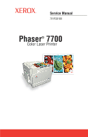 1
1 -
 2
2 -
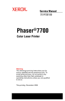 3
3 -
 4
4 -
 5
5 -
 6
6 -
 7
7 -
8
-
9
-
10
-
11
-
12
-
13
-
14
-
15
-
16
-
17
-
18
-
19
-
20
-
21
-
22
-
23
-
24
-
25
-
26
-
27
-
28
-
29
-
30
-
31
-
32
-
33
-
34
-
35
-
36
-
37
-
38
-
39
-
40
-
41
-
42
-
43
-
44
-
45
-
46
-
47
-
48
-
49
-
50
-
51
-
52
-
53
-
54
-
55
-
56
-
57
-
58
-
59
-
60
-
61
-
62
-
63
-
64
-
65
-
66
-
67
-
68
-
69
-
70
-
71
-
72
-
73
-
74
-
75
-
76
-
77
-
78
-
79
-
80
-
81
-
82
-
83
-
84
-
85
-
86
-
87
-
88
-
89
-
90
-
91
-
92
-
93
-
94
-
95
-
96
-
97
-
98
-
99
-
100
-
101
-
102
-
103
-
104
-
105
-
106
-
107
-
108
-
109
-
110
-
111
-
112
-
113
-
114
-
115
-
116
-
117
-
118
-
119
-
120
-
121
-
122
-
123
-
124
-
125
-
126
-
127
-
128
-
129
-
130
-
131
-
132
-
133
-
134
-
135
-
136
-
137
-
138
-
139
-
140
-
141
-
142
-
143
-
144
-
145
-
146
-
147
-
148
-
149
-
150
-
151
-
152
-
153
-
154
-
155
-
156
-
157
-
158
-
159
-
160
-
161
-
162
-
163
-
164
-
165
-
166
-
167
-
168
-
169
-
170
-
171
-
172
-
173
-
174
-
175
-
176
-
177
-
178
-
179
-
180
-
181
-
182
-
183
-
184
-
185
-
186
-
187
-
188
-
189
-
190
-
191
-
192
-
193
-
194
-
195
-
196
-
197
-
198
-
199
-
200
-
201
-
202
-
203
-
204
-
205
-
206
-
207
-
208
-
209
-
210
-
211
-
212
-
213
-
214
-
215
-
216
-
217
-
218
-
219
-
220
-
221
-
222
-
223
-
224
-
225
-
226
-
227
-
228
-
229
-
230
-
231
-
232
-
233
-
234
-
235
-
236
-
237
-
238
-
239
-
240
-
241
-
242
-
243
-
244
-
245
-
246
-
247
-
248
-
249
-
250
-
251
-
252
-
253
-
254
-
255
-
256
-
257
-
258
-
259
-
260
-
261
-
262
-
263
-
264
-
265
-
266
-
267
-
268
-
269
-
270
-
271
-
272
-
273
-
274
-
275
-
276
-
277
-
278
-
279
-
280
-
281
-
282
-
283
-
284
-
285
-
286
-
287
-
288
-
289
-
290
-
291
-
292
-
293
-
294
-
295
-
296
-
297
-
298
-
299
-
300
-
301
-
302
-
303
-
304
-
305
-
306
-
307
-
308
-
309
-
310
-
311
-
312
-
313
-
314
-
315
-
316
-
317
-
318
-
319
-
320
-
321
-
322
-
323
-
324
-
325
-
326
-
327
-
328
-
329
-
330
-
331
-
332
-
333
-
334
-
335
-
336
-
337
-
338
-
339
-
340
-
341
-
342
-
343
-
344
-
345
-
346
-
347
-
348
-
349
-
350
-
351
-
352
-
353
-
354
-
355
-
356
-
357
-
358
-
359
-
360
-
361
-
362
-
363
-
364
-
365
-
366
-
367
-
368
-
369
-
370
-
371
-
372
-
373
-
374
-
375
-
376
-
377
-
378
-
379
-
380
-
381
-
382
-
383
-
384
-
385
-
386
-
387
-
388
-
389
-
390
-
391
-
392
-
393
-
394
-
395
-
396
-
397
-
398
-
399
-
400
-
401
-
402
-
403
-
404
-
405
-
406
 |
 |
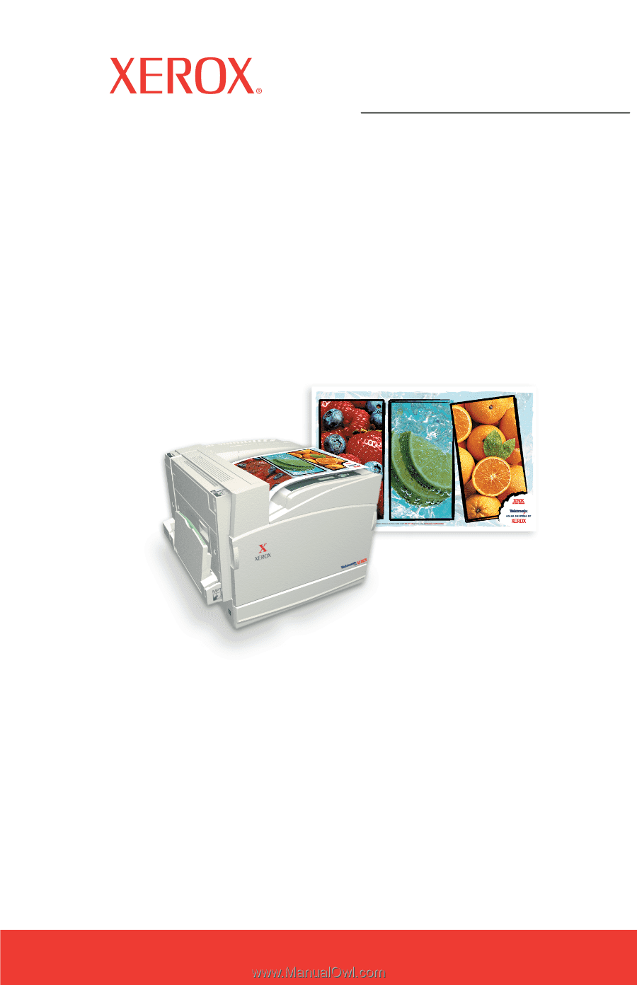
Service Manual
Phaser
®
7700
701P28180
Color Laser Printer