| Section |
Page |
| Phaser 7700 Service Manual |
3 |
| User Safety Summary |
5 |
| Terms in Manual |
5 |
| Terms on Product |
5 |
| Power Source |
6 |
| Power Supply and Electrical Components |
6 |
| Mechanical Components |
6 |
| Laser Components |
7 |
| Fuser Components |
7 |
| Safety Components |
7 |
| Warning Labels |
7 |
| Safety Instructions |
8 |
| Care of Product |
8 |
| Ground the Product |
8 |
| Service Safety Summary |
9 |
| General Guidelines |
9 |
| Class 1 Laser Product |
9 |
| Federal Communication Commision Compliance |
10 |
| Canadian Notice |
11 |
| Avis Canadien |
11 |
| European Notice |
11 |
| Hinweis |
11 |
| ESD Precautions |
12 |
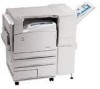
| Figure 1-1 The Phaser 7700 Color Laser Printer (shown with the High-Capacity Feeder) |
31 |
| Phaser 7700 Printer Overview |
32 |
| Phaser 7700 Printer Overview |
32 |
| Printer RAM and Printer Capabilities |
34 |
| CRC Life Counter Behavior |
35 |
| Table 1-1 CRC Life |
35 |
| Engine Control Interface and Power Supply Boards |
36 |
| Figure 1-2 Engine Control Interface and Power Supply Boards |
36 |
| Power Supplies |
37 |
| Figure 1-3 Power Supplies |
37 |
| Engine Control and Image Processor Boards |
38 |
| Figure 1-4 Engine Control and Image Processor Boards |
38 |
| Auxiliary Feeder Control Board |
39 |
| Figure 1-5 Auxiliary Feeder Control Board |
39 |
| Print Engine Sensors and Switches |
40 |
| Figure 1-6 Print Engine Sensors and Switches |
40 |
| Print Engine Sensors and Switches (cont’d.) |
41 |
| Figure 1-7 Print Engine Sensors and Switches (cont’d.) |
41 |
| Auxiliary Feeder Sensors and Switches |
42 |
| Figure 1-8 Auxiliary Feeder Sensors and Switches |
42 |
| Auxiliary Feeder Actuators and Clutches |
43 |
| Figure 1-9 Auxiliary Feeder Actuators and Clutches |
43 |
| Print Engine Solenoids, Actuators, and Clutches |
44 |
| Figure 1-10 Print Engine Solenoids, Actuators, and Clutches |
44 |
| Print Engine and Auxiliary Feeder Interlocks and Sensors |
45 |
| Figure 1-11 Print Engine and Auxiliary Feeder Interlocks and Sensors |
45 |
| Image Processor Board |
46 |
| Figure 1-12 Image Processor Board |
46 |
| Assemblies of the Print Engine |
47 |
| Figure 1-13 Assemblies of the Print Engine |
47 |
| Assemblies of the Print Engine (cont’d.) |
48 |
| Figure 1-14 Assemblies of the Print Engine (cont’d.) |
48 |
| Assemblies of the Print Engine (cont’d.) |
49 |
| Figure 1-15 Assemblies of the Print Engine (cont’d.) |
49 |
| Auxiliary Feeder Assemblies |
50 |
| Figure 1-16 Auxiliary Feeder Assemblies |
50 |
| Front Panel Description |
51 |
| LED indicators |
51 |
| Figure 1-17 Front Panel |
51 |
| Table 1-2 Front Panel Key Descriptions |
51 |
| Front Panel Shortcuts |
52 |
| Table 1-3 Front Panel Shortcuts |
52 |
| Rear Panel |
53 |
| Connectors |
53 |
| Figure 1-18 Printer Rear Connections |
53 |
| Table 1-4 Rear Panel DIP Switch Settings |
53 |
| Printer Specifications |
54 |
| Physical Dimensions and Clearances |
54 |
| Table 1-5 Physical Dimensions of the Printer |
54 |
| Table 1-6 Physical Dimensions of Lower Tray Feeder |
54 |
| Figure 1-19 Printer Clearances |
54 |
| Table 1-7 Functional Specifications |
55 |
| Table 1-8 Electrical Specifications |
55 |
| Table 1-9 Environmental Specifications |
56 |
| Supported Paper Weights, Page Sizes and Print Area |
57 |
| Table 1-10 Specialty Paper |
58 |
| Table 1-11 Print Area |
58 |
| Error Messages |
61 |
| Troubleshooting Error Codes |
61 |
| Chain / Link |
61 |
| Where do they come from? |
61 |
| Why are they here? |
61 |
| Diagnostics, Error Codes, and Messages |
61 |
| Error Messages |
61 |
| Troubleshooting Error Codes |
61 |
| System Boot Sequence |
62 |
| Power On Self Test (POST) |
62 |
| POST Faults |
63 |
| Fault Reporting Devices |
63 |
| LED Blink Patterns |
63 |
| POST Diagnostics Test Descriptions |
64 |
| Table 2-1 POST Diagnostics Test Descriptions |
64 |
| Service Diagnostics |
65 |
| Entering Service Diagnostics Mode |
65 |
| Service Diagnostics Test Menu Functions |
66 |
| Table 2-2 Service Diagnostics Test Menu Functions |
66 |
| Error Codes and Messages Troubleshooting |
76 |
| Voltage Measurements |
76 |
| Figure 2-1 Voltage Measurement Point Locations |
76 |
| Fuser Connector Pin Locations |
77 |
| Fig 2-2 Fuser Connector Pin Locations |
77 |
| Troubleshooting Network Problems |
118 |
| Operating System and Application Problems |
118 |
| Media Jams and the Paper Path |
118 |
| Print Image Quality Problems |
118 |
| Troubleshooting Power Supplies and Interlocks |
119 |
| Troubleshooting AC Power |
119 |
| Troubleshooting the Low-voltage Power Supplies |
119 |
| Troubleshooting Power Supplies and Interlocks |
119 |
| Troubleshooting AC Power |
119 |
| Troubleshooting Low-Voltage Power Supplies |
119 |
| Troubleshooting the +3.3 VDC and +5 VDC LVPS |
120 |
| Troubleshooting the +24 VDC LVPS |
120 |
| Interlock Circuit Diagram |
121 |
| Figure 3-1 Circuit Diagram |
121 |
| The +24 VDC Interlock Circuit |
121 |
| The +5 VDC Interlock Circuit |
122 |
| Troubleshooting When the Printer Does Not Come to a “Ready” State |
123 |
| Printer Does Nothing When Power Switched On |
123 |
| Fans On, Front Panel LED Never On |
123 |
| Fans On, Front Panel LED is Red, No Front Panel message |
123 |
| Front Panel Continually Displays the Xerox Phaser 7700 Splash Screen |
123 |
| Front Panel Continually Displays \ |
123 |
| Front Panel displays \ |
124 |
| Troubleshooting - Printer Comes to a “Ready” State |
124 |
| False LH Door, RH Door, or Front Door Open Messages |
124 |
| False \ |
124 |
| False \ |
124 |
| Tray 1 Will Not Lift |
125 |
| Tray 2, 3 or 4 Will Not Lift |
125 |
| Tray 2, 3 and 4 Will Not Lift or Printer Will Not Recognize the Auxiliary Feeder |
126 |
| Printer Will Not Recognize the Finisher |
126 |
| Troubleshooting the Toner Dispense/Auger/Developer System |
127 |
| Checking the Toner Cartridge |
127 |
| Figure 3-2 Toner Cartridge Gear |
127 |
| Checking the Toner Auger System |
128 |
| Figure 3-3 Toner Cartridge |
128 |
| Figure 3-4 Toner Dispense Assembly |
129 |
| Figure 3-5 Toner Port |
130 |
| Checking the Developer ATC Sensor |
131 |
| Checking the Developer |
132 |
| Tips |
132 |
| Figure 3-6 Developer Housing |
133 |
| Operation System and Application Problems |
134 |
| Macintosh Printing Problems |
134 |
| Windows Printing Problems |
134 |
| Media Jams and the Paper Path |
136 |
| Media-based Problems |
136 |
| Multiple-sheet Pick |
136 |
| Mis-pick |
136 |
| Skewed Image |
136 |
| Damaged Prints |
137 |
| Fuser Jams |
137 |
| Exit Jams |
137 |
| Print Image Quality Problems |
138 |
| Light (undertone) Prints (all colors) |
138 |
| Blank Prints |
138 |
| One Color is Faded or Missing |
139 |
| Missing Band in Direction of Paper Travel |
140 |
| Streaks in Direction of Paper Travel |
141 |
| Streaks Parallel with the Leading Edge |
142 |
| Random Missing Spots |
143 |
| Random Spotting |
143 |
| Single Color |
143 |
| All Colors |
144 |
| Repetitive Mark Appears on Each Print |
144 |
| Background Contamination |
145 |
| Unfused Image or Image Easily Rubs Off of Page |
146 |
| Toner on Back of Print |
147 |
| Print is Mottled |
148 |
| Image Mis-registered on Paper |
149 |
| Residual Image or Ghosting |
150 |
| Light Bands, Dark Bands, or Mottled Prints |
151 |
| Adjustments and Calibration |
153 |
| Internal Hard Drive |
153 |
| Registration Control (RegiCon) Adjustment Overview |
154 |
| Coarse RegiCon Initialization |
154 |
| Figure 4-1 Coarse RegiCon Initialization |
154 |
| Coarse and Fine Skew Adjustments |
155 |
| Figure 4-2 Coarse and Fine Skew Adjustments |
155 |
| In/Out Skew Adjustment |
155 |
| Figure 4-3 In/Out Skew Adjustment |
155 |
| Center Skew Adjustment |
156 |
| Figure 4-4 Center Skew Adjustment |
156 |
| Processes of the RegiCon Adjustment |
157 |
| Check Print-quality |
157 |
| Preparation for RegiCon |
157 |
| Registration Control Procedures |
160 |
| RegiCon Flowchart |
163 |
| Figure 4-5 RegiCon Flowchart |
163 |
| Step 1: Belt Edge Learn |
164 |
| Step 2: RegiCon #4 Coarse Skew Adjustment |
165 |
| Step 3: RegiCon #1 Fine Skew Adjustment |
167 |
| Step 4: RegiCon #2 In/Out Skew Adjustment |
168 |
| Step 5: RegiCon #3 Center Skew Adjustment |
169 |
| Coarse RegiCon Initialization |
170 |
| Figure 4-6 Grid 1-Dot Pattern Orientation for A-size Paper |
170 |
| Figure 4-7 Grid 1-Dot pattern annotations |
171 |
| ATC Sensor Setup |
172 |
| Additional Information |
172 |
| Cleaning and Maintenance |
173 |
| Service Preventive Maintenance Procedure |
173 |
| Recommended Tools |
173 |
| Cleaning |
173 |
| Resetting NVRAM |
175 |
| PostScript NVRAM Resets |
175 |
| Restore Factory Settings (color) |
175 |
| Restore Previous Settings (color) |
175 |
| Restore Factory Settings (margins) |
176 |
| Reset Calibrations (color, margins, paper) |
176 |
| Resetting All Printer Default Settings (NVRAM) |
176 |
| Resetting Engine NVRAM |
176 |
| Resetting Job Defaults |
177 |
| Resetting Network Setup Values to Default |
177 |
| Resetting Accumulator Belt Life |
177 |
| Resetting Belt Cleaner Assembly Life |
178 |
| Resetting Transfer Roller Life |
178 |
| Service Diagnostics NVRAM Resets |
179 |
| PostScript NVRAM Reset |
179 |
| Clear Tech Rep Faults |
179 |
| Reset CRU Life Counters |
179 |
| Reset Engine NVRAM |
180 |
| Store Engine NVRAM |
180 |
| Removal and Replacement Procedures |
181 |
| Contents |
182 |
| RRP 1 Rear Cover Assembly |
184 |
| Figure 7-1 Rear Cover Assembly |
184 |
| RRP 2 Right Side Cover Assembly |
185 |
| Figure 7-2 Right Side Cover Assembly |
185 |
| RRP 3 Top Cover Assembly |
186 |
| Figure 7-3 Top Cover Assembly |
186 |
| RRP 4 Front Panel Assembly |
187 |
| Figure 7-4 Control Panel Assembly |
187 |
| RRP 5 Rear Cover, Top Rear Power Switch Cover and LH Rear Mid Cover |
188 |
| Figure 7-5 Top Rear Power Switch Cover and Left-Hand Rear Mid Cover |
188 |
| RRP 6 Left-Hand Lower Cover Assembly |
190 |
| Figure 7-6 Left-Hand Lower Cover Assembly |
190 |
| RRP 7 Front Cover Assembly |
191 |
| Figure 7-7 Front Cover Assembly |
191 |
| RRP 8 Fuser Front Cover |
192 |
| Figure 7-8 Fuser Front Cover |
192 |
| RRP 9 Rear Shield |
193 |
| Figure 7-9 Rear Shield |
193 |
| RRP 10 Rear Shield Bracket |
194 |
| Figure 7-10 Rear Shield Bracket |
194 |
| RRP 11 24 VDC Power Supply Shield |
195 |
| Figure 7-11 24 VDC Power Supply Shield |
195 |
| RRP 12 Multi-Purpose Tray (MPT) Assembly |
196 |
| Figure 7-12 MPT Assembly |
196 |
| RRP 13 Multi-Purpose Tray Paper Pick Rollers |
197 |
| Figure 7-13 Multi-Purpose Tray Pick Rollers |
197 |
| RRP 14 Left-Hand Cover Assembly (Left-Hand Door) |
198 |
| Figure 7-14 Left-Hand Cover Assembly (Left-Hand Door) |
198 |
| Figure 7-15 Damper Teeth Alignment |
199 |
| RRP 15 Duplex Chute |
200 |
| Figure 7-16 Duplex Chute |
200 |
| RRP 16 Duplex Unit Assembly |
201 |
| Figure 7-17 Duplex Unit Assembly |
201 |
| RRP 17 Transfer Roller Assembly (2nd BTR) |
202 |
| Figure 7-18 Transfer Roller Assembly (2nd BTR) |
202 |
| RRP 18 Duplex Transport Assembly |
203 |
| Figure 7-19 Inverter Transport Assembly |
203 |
| RRP 19 Fuser Unit |
204 |
| Figure 7-20 Fuser Unit |
204 |
| RRP 20 Registration Transport Assembly |
205 |
| Figure 7-21 Registration Transport Assembly |
205 |
| RRP 21 Shutter Solenoid Assembly |
206 |
| Figure 7-22 Shutter Solenoid Assembly |
206 |
| RRP 22 Tray 1 Feeder Assembly and Paper Lift Motor |
207 |
| Figure 7-23 Tray 1 Feeder Assembly |
207 |
| RRP 23 Waste Cartridge Sensor Holder |
208 |
| Figure 7-24 Waste Cartridge, Waste Cartridge Cover and Waste Cartridge Sensor Holder |
208 |
| RRP 24 Print Cartridge Plate Cover |
209 |
| Figure 7-25 Print Cartridge Plate Cover (plastic) |
209 |
| RRP 25 Dispense Assembly |
210 |
| Figure 7-26 Dispense Assembly |
210 |
| RRP 26 Print Cartridge Plate Assembly |
212 |
| Figure 7-27 Print Cartridge Plate Assembly |
212 |
| Figure 7-28 Print Cartridge Plate Assembly (cont’d.) |
213 |
| RRP 27 Developer Housing Assembly |
215 |
| Figure 7-29 Developer Housing Assembly |
215 |
| RRP 28 New Developer Housing Assembly Charging |
216 |
| Figure 7-30 Developer Housing Assembly Recharge |
216 |
| RRP 29 Toner Dispense Motor Assembly |
218 |
| Figure 7-31 Toner Dispense Motor Assembly |
218 |
| RRP 30 Steering Drive Assembly |
219 |
| Figure 7-32 Steering Drive Assembly |
219 |
| RRP 31 Waste Toner Agitator Motor Assembly |
220 |
| Figure 7-33 Waste Toner Agitator Motor Assembly. |
220 |
| RRP 32 Mark-On-Belt (MOB) Sensor |
221 |
| Figure 7-34 Mark-On-Belt Sensor |
221 |
| RRP 33 Exit Transport Assembly |
222 |
| Figure 7-35 Exit Transport Assembly |
222 |
| Figure 7-36 Reconfigured Inverter |
223 |
| Figure 7-37 Parts No Longer Installed |
223 |
| Figure 7-38 Interlock Actuator and Spacers |
224 |
| RRP 34 Fuser Fan Assembly |
225 |
| Figure 7-39 Fuser Fan Assembly |
225 |
| RRP 35 Accumulator Belt Assembly |
226 |
| Figure 7-40 Accumulator Belt Assembly |
226 |
| RRP 36 Belt Cleaner Assembly |
228 |
| Figure 7-41 Belt Cleaner Assembly |
228 |
| RRP 37 Waste Auger Assembly |
229 |
| Figure 7-42 Waste Auger Assembly |
229 |
| RRP 38 Laser Unit |
230 |
| Figure 7-43 Laser Unit Assembly |
230 |
| Figure 7-44 Laser Unit Label |
231 |
| RRP 39 Image Processor Board Assembly |
232 |
| Figure 7-45 Image Processor Board Assembly. |
232 |
| RRP 40 Internal Hard Drive |
233 |
| Figure 7-46 Internal Hard Drive |
233 |
| RRP 41 Electrical Chassis (Card Cage) Assembly |
234 |
| Figure 7-47 Electrical Chassis Assembly |
234 |
| RRP 42 Engine Control Board |
236 |
| Figure 7-48 Engine Control Board |
236 |
| RRP 43 Engine Control Interface Board |
237 |
| Figure 7-49 Engine Control Interface Board |
237 |
| RRP 44 T1 and T3 High-voltage Power Supplies |
238 |
| Figure 7-50 T1 and T3 High-voltage Power Supplies |
238 |
| RRP 45 3.3 VDC and 5 VDC Low-Voltage Power Supplies and Bracket |
240 |
| Figure 7-51 3.3 VDC and 5 VDC Low-Voltage Power Supplies |
240 |
| RRP 46 LD Power Relay |
241 |
| Figure 7-52 LD Power Relay |
241 |
| RRP 47 +24 VDC Low-voltage Power Supply, Fan and Bracket |
242 |
| Figure 7-53 Low-voltage Power Supply, Fan and Bracket |
242 |
| RRP 48 T2 High-Voltage Power Supply |
243 |
| Figure 7-54 T2 High-Voltage Power Supply |
243 |
| RRP 49 Chassis AC Power Assembly |
244 |
| Figure 7-55 Chassis AC Power Assembly |
244 |
| RRP 50 Main Drive Assembly |
245 |
| Figure 7-56 Main Drive Assembly |
245 |
| RRP 51 Accumulator Belt Drive Assembly |
247 |
| Figure 7-57 Accumulator Belt Drive Assembly |
247 |
| RRP 52 Developer Drive Assembly |
248 |
| Figure 7-58 Developer Drive Assembly |
248 |
| RRP 53 Print Cartridge Drive Assembly |
249 |
| Figure 7-59 Print Cartridge Drive Assembly |
249 |
| RRP 54 Tray 1 Paper-Select Switches |
250 |
| Figure 7-60 Tray 1 Paper-Select Switches |
250 |
| RRP 55 Main Lever Assembly Right and Left-Hand Jacks |
251 |
| Figure 7-61 Main Lever, Right-Hand and Left-Hand Jacks |
251 |
| Figure 7-62 Lift Pin Alignment |
253 |
| Figure 7-63 Cover Screw Location |
253 |
| Figure 7-64 Cover Removed |
254 |
| Figure 7-65 Tension Spring Location |
254 |
| Figure 7-66 Front and Rear Gears Aligned |
254 |
| RRP 56 Auxiliary Feeder Covers |
255 |
| Figure 7-67 Auxiliary Feeder Covers |
255 |
| RRP 57 Auxiliary Feeder Cover Assembly |
256 |
| Figure 7-68 High-Capacity Feeder (HCF) Cover Assembly |
256 |
| RRP 58 High-Capacity Feeder (HCF) Tray 3 |
257 |
| Figure 7-69 High-Capacity Feeder (HCF) Tray 3 |
257 |
| RRP 59 High-Capacity Feeder (HCF) Tray 4 and Paper Transport |
258 |
| Figure 7-70 High-Capacity Feeder (HCF) Tray 4 and Paper Transport |
258 |
| RRP 60 Auxiliary Feeder Control Boards |
259 |
| Figure 7-71 LTD Control or HCF Control Board |
259 |
| RRP 61 Auxiliary Feeders Motor Assemblies |
260 |
| Figure 7-72 Transport Motor Assembly |
260 |
| RRP 62 Auxiliary Feeder Paper-Select Switches |
261 |
| Figure 7-73 Paper-Select Switches |
261 |
| RRP 63 Auxiliary Feeder Paper Feed Motor Assembly |
262 |
| Figure 7-74 Paper Feed Motor Assembly and Chute (LTA & HCF) |
262 |
| RRP 64 Bracket Assembly, Left-Hand and Right-Hand Gear (HCF) |
263 |
| Figure 7-75 Bracket Assembly, Gear RH & Gear LH (HCF) |
263 |
| FRU Parts List |
265 |
| PL 8-1 Accumulator Belt FRUs |
266 |
| Figure 8-1 Accumulator Belt FRUs |
266 |
| Table 8-1 Accumulator Belt FRUs List |
266 |
| PL 8-2 Left-Hand Door FRUs |
267 |
| Figure 8-2 Left-Hand Door FRUs |
267 |
| Table 8-2 Left-Hand Door FRUs List |
268 |
| PL 8-3 Media Trays FRUs |
269 |
| Figure 8-3 Media Trays FRUs |
269 |
| Table 8-3 Media Trays FRUs List |
269 |
| PL 8-4 Duplex Unit FRUs |
270 |
| Figure 8-4 Duplex Unit FRUs |
270 |
| Table 8-4 Duplex Unit FRUs List |
270 |
| PL 8-5 Cover FRUs |
271 |
| Figure 8-5 Cover FRUs |
271 |
| Table 8-5 Cover FRUs List |
271 |
| PL 8-6 Cover FRUs (cont’d.) |
272 |
| Figure 8-6 Cover FRUs (cont’d.) |
272 |
| Table 8-6 Cover FRUs (cont’d.) List |
272 |
| PL 8-7 Cover FRUs (cont’d.) |
273 |
| Figure 8-7 Cover FRUs (cont’d.) |
273 |
| Table 8-7 Covers FRUs List (cont’d.) |
274 |
| PL 8-8 Switch and Sensor FRUs |
275 |
| Figure 8-8 Switch and Sensor FRUs |
275 |
| Table 8-8 Switch and Sensor FRUs List |
276 |
| PL 8-9 Switch and Sensor FRUs (cont’d.) |
277 |
| Figure 8-9 Switch and Sensor FRUs (cont’d.) |
277 |
| Table 8-9 Switch and Sensor FRUs List (cont’d.) |
278 |
| PL 8-10 Circuit Boards FRUs |
279 |
| Figure 8-10 Circuit Boards FRUs |
279 |
| Table 8-10 Circuit Board FRUs List |
280 |
| PL 8-11 Power Supplies FRUs |
281 |
| Figure 8-11 Power Supplies FRUs |
281 |
| Table 8-11 Power Supplies FRUs List |
282 |
| PL 8-12 Power Supplies FRUs (cont’d.) |
283 |
| Figure 8-12 Power Supplies FRUs (cont’d.) |
283 |
| Table 8-12 Power Supplies FRUs List (cont’d.) |
284 |
| PL 8-13 Motors/Drivers FRUs |
285 |
| Figure 8-13 Motors/Drivers FRUs |
285 |
| Table 8-13 Motors / Drivers FRUs List |
286 |
| PL 8-14 Electrophotographic Components FRUs |
287 |
| Figure 8-14 Electrophotographic Components FRUs |
287 |
| Table 8-14 Electrophotographic Components FRUs List |
288 |
| PL 8-15 Electrophotographic Components FRUs (cont’d.) |
289 |
| Figure 8-15 Electrophotographic Components FRUs (cont’d.) |
289 |
| Table 8-15 Electrophotographic Components FRUs List (cont’d.) |
290 |
| PL 8-16 Multi-Purpose Tray FRUs |
291 |
| Figure 8-16 Multi-Purpose Tray FRUs |
291 |
| Table 8-16 Multi-Purpose Tray (MPT) FRUs List |
292 |
| PL 8-17 Paper Feed FRUs |
293 |
| Figure 8-17 Paper Feed FRUs |
293 |
| Table 8-17 Paper Feed FRUs List |
294 |
| PL 8-18 Paper Feed FRUs (cont’d.) |
295 |
| Figure 8-18 Paper feed FRUs (cont’d.) |
295 |
| Table 8-18 Paper Feed FRUs List (cont’d.) |
296 |
| PL 8-19 Fans FRUs |
297 |
| Figure 8-19 Fans FRUs |
297 |
| Table 8-19 Fans FRUs List |
297 |
| PL 8-20 Lift Components FRUs |
298 |
| Figure 8-20 Lift Components FRUs |
298 |
| Table 8-20 Lift Components FRUs List |
299 |
| PL 8-21 Wiring FRUs |
300 |
| Figure 8-21 Wiring FRUs |
300 |
| Table 8-21 Wiring FRUs List |
301 |
| PL 8-22 Auxiliary Feeder FRUs |
302 |
| Figure 8-22 Auxiliary Feeder FRUs |
302 |
| Table 8-22 Auxiliary Feeders FRUs List |
303 |
| PL 8-23 Lower Tray Deck (LTD) FRUs |
304 |
| Figure 8-23 Lower Tray Deck (LTD) FRUs |
304 |
| Table 8-23 Lower Tray Deck (LTD) FRUs List |
305 |
| PL 8-24 Lower Tray Deck (LTD) FRUs (cont’d.) |
306 |
| Figure 8-24 Lower Tray Deck (LTD) FRUs (cont’d.) |
306 |
| Table 8-24 Lower Tray Deck (LTD) FRUs List (cont’d.) |
306 |
| PL 8-25 High-Capacity Feeder FRUs |
307 |
| Figure 8-25 High-Capacity Feeder FRUs |
307 |
| Table 8-25 High-Capacity Feeder FRUs List |
307 |
| PL 8-26 High-Capacity Feeder FRUs (cont’d.) |
308 |
| Figure 8-26 High-Capacity Feeder FRUs (cont’d.) |
308 |
| Table 8-26 High-Capacity Feeder FRUs List (cont’d.) |
308 |
| PL 8-27 High-Capacity Feeder FRUs (cont’d.) |
309 |
| Figure 8-27 High-Capacity Feeder FRUs (cont’d.) |
309 |
| Table 8-27 High-Capacity Feeder FRUs List (cont’d.) |
309 |
| PL 8-28 High-Capacity Feeder FRUs (cont’d.) |
310 |
| Figure 8-28 High-Capacity Feeder FRUs (cont’d.) |
310 |
| Table 8-28 High-Capacity Feeder FRUs List (cont’d.) |
310 |
| PL 8-29 High-Capacity Feeder FRUs (cont’d.) |
311 |
| Figure 8-29 High-Capacity Feeder FRUs (cont’d.) |
311 |
| Table 8-29 High-Capacity Feeder FRUs (cont’d.) |
311 |
| Kits |
312 |
| Table 8-30 Kits |
312 |
| Manual Packs & Service Manual |
313 |
| Table 8-31 Manual Packs & Service Manual |
313 |
| Software |
314 |
| Table 8-32 Software |
314 |
| Supplies and Accessories |
314 |
| Table 8-33 Supplies |
314 |
| Table 8-34 Accessories |
315 |
| Recommended Service Tools |
315 |
| Table 8-35 Recommended Tools List |
315 |
| Test Prints |
317 |
| Analyzing the Test Print |
318 |
| Print Color Test Prints |
319 |
| Interpreting Solid Fill Test Prints |
320 |
| Diagnostics Mode |
321 |
| Laser Check |
321 |
| Halftones |
321 |
| Grid 1-dot |
322 |
| Fast Scan 8 |
323 |
| Wiring Diagrams |
325 |
| Phaser 7700 Finisher |
343 |
| Figure 11-1 Phaser 7700 Color Laser Printer with the Finisher Option |
343 |
| Finisher Overview |
344 |
| General Information |
345 |
| Table 11-1 Finisher Specifications |
345 |
| Figure 11-2 Dimensions of the Finisher |
345 |
| Assemblies of the Finisher |
347 |
| Figure 11-3 Assemblies of the Finisher |
347 |
| Internal Assemblies of the Finisher |
348 |
| Figure 11-4 Internal Assemblies of the Finisher |
348 |
| Horizontal Transport Sensor, Interlock, and Switch Locator Map |
349 |
| Figure 11-5 Horizontal Transport Sensor, Interlock and Switch Locator Map |
349 |
| Finisher Sensor, Interlock, and Switch Locator Map |
350 |
| Figure 11-6 Finisher Sensor, Interlock, and Switch Locator Map |
350 |
| Finisher Sensor, Interlock, and Switch Locator Map |
351 |
| Figure 11-7 Finisher Sensor, Interlock, and Switch Locator |
351 |
| Removal and Replacement Procedures |
353 |
| RRP 66 Horizontal Transport Assembly |
354 |
| Figure 11-8 Horizontal Transport Assembly |
354 |
| RRP 67 Horizontal Transport Top Open, Front, and Rear Cover |
355 |
| Figure 11-9 H-Transport Top Open, Front and Rear Covers |
355 |
| RRP 68 Horizontal Transport Entrance Upper Cover Assembly |
356 |
| Figure 11-10 Horizontal Transport Entrance Upper Cover |
356 |
| RRP 69 Horizontal Transport Belts |
357 |
| Figure 11-11 Horizontal Transport Belts |
357 |
| RRP 70 Horizontal Transport Entrance Sensor and Top Tray Full Sensor |
358 |
| Figure 11-12 H-Tra Entrance and Top Tray Full Sensor |
358 |
| RRP 71 Gate-In Solenoid Assembly |
359 |
| Figure 11-13 H-Transport Gate-In Solenoid |
359 |
| RRP 72 Finisher Covers |
360 |
| Figure 11-14 Finisher Covers |
360 |
| RRP 73 Stack Height-Sensor Assembly |
362 |
| Figure 11-15 Stack Height-Sensor Assembly |
362 |
| RRP 74 Stacker Paper-Sensor Assembly |
363 |
| Figure 11-16 Stacker Paper-Sensor Assembly |
363 |
| RRP 75 Set Clamp Clutch and Gear |
364 |
| Figure 11-17 Set Clamp Clutch and Gear |
364 |
| RRP 76 Eject Roll Assembly |
365 |
| Figure 11-18 Eject Roll |
365 |
| RRP 77 Finisher Control Board, Bracket, and Shield |
366 |
| Figure 11-19 Finisher Control Board, Bracket, and Shield |
366 |
| RRP 78 Stacker Motor Assembly |
368 |
| Figure 11-20 Stacker Motor Assembly |
368 |
| RRP 79 Paddle Shaft |
369 |
| Figure 11-21 Paddle Shaft |
369 |
| RRP 80 Paper Transport Motor (Motor Assembly Main) |
370 |
| Figure 11-22 Paper Transport Motor |
370 |
| RRP 81 Cam Bracket Assembly |
371 |
| Figure 11-23 Cam Bracket Assembly |
371 |
| RRP 82 Staple Unit Assembly and Motor |
372 |
| Figure 11-24 Staple Unit Assembly |
372 |
| RRP 83 Compiler Tray |
374 |
| Figure 11-25 Compiler Tray |
374 |
| Finisher FRU Parts List |
375 |
| Figure 11-26 Finisher Unit Main Assemblies FRUs |
375 |
| Table 11-2 Finisher Unit Main Assemblies FRUs List |
376 |
| Figure 11-27 Finisher Covers FRUs |
377 |
| Table 11-3 Finisher Covers FRUs List |
377 |
| Figure 11-28 Finisher Stand FRUs |
378 |
| Table 11-4 Finisher Stand FRUs List |
379 |
| Figure 11-29 Gate Unit FRUs |
380 |
| Table 11-5 Gate Unit FRUs List |
381 |
| Figure 11-30 Horizontal Transport Assembly FRUs |
382 |
| Table 11-6 Horizontal Transport Assembly FRUs List |
383 |
| Figure 11-31 Horizontal Transport Assembly FRUs (cont’d.) |
384 |
| Table 11-7 Horizontal Transport Assembly FRUs List (cont’d.) |
385 |
| Figure 11-32 Top Cover and Eject Roll FRUs |
386 |
| Table 11-8 Top Cover and Eject Roll FRUs List |
387 |
| Figure 11-33 Paper Transport Assembly FRUs |
388 |
| Table 11-9 Paper Transport Assembly FRUs List |
389 |
| Figure 11-34 Paper Transport Assembly FRUs (cont’d.) |
390 |
| Table 11-10 Paper Transport Assembly FRUs List (cont’d.) |
391 |
| Figure 11-35 Staple Unit Assembly FRUs |
392 |
| Table 11-11 Staple Unit Assembly FRUs List |
393 |
| Figure 11-36 Compiler Tray Assembly FRUs |
394 |
| Table 11-12 Compiler Tray Assembly FRUs List |
395 |
| Figure 11-37 Stacker Elevator Assembly FRUs |
396 |
| Table 11-13 Stacker Elevator Assembly FRUs List |
397 |
| Figure 11-38 Exit Assembly FRUs |
398 |
| Table 11-14 Exit Assembly FRUs List |
399 |
| Figure 11-39 Electrical FRUs |
400 |
| Table 11-15 Electrical FRUs List |
400 |
| Finisher Wiring Diagrams |
401 |
| Figure 12-1 Block diagram of the Finisher |
402 |
 1
1 43
43 44
44 45
45 46
46 47
47 48
48 49
49 50
50 51
51 52
52 53
53

