Xerox DC240 x-rite @ DTP32R and DTP32HS Operator's Manual - Page 8
Top View
 |
View all Xerox DC240 manuals
Add to My Manuals
Save this manual to your list of manuals |
Page 8 highlights
DTP32HS DENSITOMETER Strip Positioning and Patch Requirements The strip width must extend a minimum of 0.75" (19mm) to the left of the alignment mark (optical path) when measuring. This ensures the read switch is activated when the strip is inserted into the instrument. TOP VIEW Alignment Mark 0.75" (19mm) min. 4" (101.6mm) max. to paper stop 0.50" (12.7mm) min. patch width Paper Stop 1.2" (30.5mm) min. leader length 0.40" (10.2mm) min. patch height 6
-
 1
1 -
2
-
 3
3 -
 4
4 -
 5
5 -
 6
6 -
 7
7 -
 8
8 -
 9
9 -
 10
10 -
 11
11 -
 12
12 -
 13
13 -
14
-
15
-
16
-
17
-
18
-
19
-
20
-
21
-
22
-
23
-
24
-
25
-
26
-
27
-
28
-
29
-
30
-
31
-
32
-
33
-
34
-
35
-
36
-
37
-
38
-
39
-
40
-
41
-
42
-
43
-
44
-
45
-
46
-
47
-
48
-
49
-
50
-
51
-
52
 |
 |

DTP32HS DENSITOMETER
6
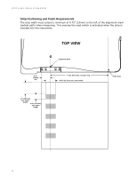
Strip Positioning and Patch Requirements
The strip width must extend a minimum of 0.75” (19mm) to the left of the alignment mark
(optical path) when measuring. This ensures the read switch is activated when the strip is
inserted into the instrument.
TOP VIEW
0.75"
(19mm)
min.
4" (101.6mm) max. to paper stop
Paper Stop
Alignment Mark
0.50" (12.7mm) min. patch width
1.2" (30.5mm)
min. leader
length
0.40" (10.2mm)
min. patch
height