Yamaha CLP-130 Owner's Manual - Page 60
CLP-130: Keyboard Stand Assembly
 |
View all Yamaha CLP-130 manuals
Add to My Manuals
Save this manual to your list of manuals |
Page 60 highlights
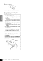
ENGLISH CLP-130: Keyboard Stand Assembly CAUTION • Be careful not to confuse parts, and be sure to install all parts in the correct direction. Please assemble in accor- dance with the sequence given below. • Assembly should be carried out by at least two persons. • Be sure to use the correct screw size, as indicated below. Use of incorrect screws can cause damage. • Be sure to tighten up all screws upon completing assembly of each unit. • To disassemble, reverse the assembly sequence given below. Have a Phillips-head (+) screwdriver ready. Remove the following parts from the package. Assembly Parts 6 × 25 mm long screws ×4 1 4 × 20 mm tapping screws ×4 4 6 × 16 mm short screws ×4 2 Cord holders × 2 4 × 12 mm thin screws ×2 3 Main unit Side panel (left) Rear panel Side panel (right) Pedal box Bundled pedal cord inside AC power cord TIP A headphone hanger is included in the CLP-130 package. You can attach a headphone hanger on the Clavinova to hang the headphones (page 12). 1. Attach the side panels to the pedal box. Side panel (left) Side panel (right) (1) Untie and straighten out the bundled cord attached to the bottom of the pedal box. Don't discard the vinyl tie, you'll need it later in step 5. (2) Use the four 6×25 mm long screws 1 to attach the pedal box. First attach one side panel, then attach the other side panel. 2. Attach the rear panel. (2) Secure the top of the rear panel to the side panel brackets using two 4×12 mm thin screws 3. (1) Place the bottom edges of the rear panel on the feet's protruding edges, with the panel slightly angled as shown in the illustration. Then, align the top part of the panel with the side panels. (3) Secure the bottom of the rear panel to the pedal box using four 4×20 mm tapping screws 4. 60 CLP-130/120 CLP-130: Keyboard Stand Assembly
-
 1
1 -
2
-
3
-
4
-
5
-
6
-
7
-
8
-
9
-
10
-
11
-
12
-
13
-
14
-
15
-
16
-
17
-
18
-
19
-
20
-
21
-
22
-
23
-
24
-
25
-
26
-
27
-
28
-
29
-
30
-
31
-
32
-
33
-
34
-
35
-
36
-
37
-
38
-
39
-
40
-
41
-
42
-
43
-
44
-
45
-
46
-
47
-
48
-
49
-
50
-
51
-
52
-
53
-
54
-
 55
55 -
 56
56 -
 57
57 -
 58
58 -
 59
59 -
 60
60 -
 61
61 -
 62
62 -
 63
63 -
 64
64 -
 65
65 -
66
-
67
-
68
-
69
-
70
-
71
-
72
-
73
-
74
-
75
-
76
-
77
-
78
-
79
-
80
 |
 |
