Yamaha CLP-320 Owner's Manual - Page 34
Keyboard Stand Assembly
 |
View all Yamaha CLP-320 manuals
Add to My Manuals
Save this manual to your list of manuals |
Page 34 highlights
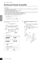
ENGLISH Keyboard Stand Assembly Keyboard Stand Assembly CAUTION • Be careful not to confuse parts, and be sure to install all parts in the correct direction. Please assemble in accor- dance with the sequence given below. • Assembly should be carried out by at least two persons. • Assemble the stand on the flat floor surface. • Be sure to use the included screws only, and insert screws of the correct size in the correct hole locations. Use of incorrect screws can cause damage or malfunction of the product. • Be sure to tighten up all screws upon completing assembly of each unit. • To disassemble, reverse the assembly sequence given below. Have a Phillips-head (+) screwdriver of the appropriate size ready. Remove all parts from the package and make sure you have all of the items. A D E B C Bundled pedal cord inside AC Power cord Assembly Parts 6 × 20 mm long screws ×4 1 4 × 20 mm tapping screws ×4 4 6 × 16 mm short screws ×4 2 Cord holders × 2 4 × 12 mm thin screws ×2 3 1. Attach (finger-tighten) C to D and E. 1-1 Untie and straighten out the bundled pedal cord. Don't discard the vinyl tie. You will need it later in step 6. 1-2 Align D and E with each end of C. 1-3 Attach D and E to C by finger-tightening the long screws 1 (6 × 20mm). E 1-2 C 1-3 D 1-1 L Headphone hanger set 4 × 10 mm thin screws ×2 5 Headphone hanger 32 34 CLP-320 Owner's Manual
-
 1
1 -
2
-
3
-
4
-
5
-
6
-
7
-
8
-
9
-
10
-
11
-
12
-
13
-
14
-
15
-
16
-
17
-
18
-
19
-
20
-
21
-
22
-
23
-
24
-
25
-
26
-
27
-
28
-
 29
29 -
 30
30 -
 31
31 -
 32
32 -
 33
33 -
 34
34 -
 35
35 -
 36
36 -
 37
37 -
 38
38 -
 39
39 -
40
-
41
-
42
-
43
-
44
 |
 |
