Yamaha CLP-320 Owner's Manual - Page 36
Connect the pedal cord., Connect the power cord to the, unit., Set the adjuster.
 |
View all Yamaha CLP-320 manuals
Add to My Manuals
Save this manual to your list of manuals |
Page 36 highlights
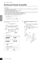
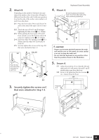
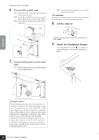
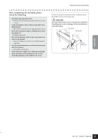
Keyboard Stand Assembly 6. Connect the pedal cord. 6-1 Insert the pedal cord plug to the pedal connector from the rear. 6-2 Attach the cord holders to the rear panel as shown, then clip the cord into the holders. 6-3 Use a vinyl tie to take up any slack in the pedal cord. 6-1 PEDAL NLET 7-2 Connect the plug on the power cord to the rear panel connector. WARNING An improper voltage setting can cause serious damage to this instrument or result in improper operation. 8. Set the adjuster. 6-3 6-2 Rotate the adjuster until it comes in firm contact with the floor surface. 9. Attach the headphone hanger. Use the included two screws 5 (4 × 10mm) to attach the hanger as shown in the illustration below. 7. Connect the power cord to the unit. 7-1 Set the voltage selector (for models that feature a voltage selector). PHONES ENGLISH 110 127 34 220 240 Voltage Selector Before connecting the AC power cord, check the setting of the voltage selector which is provided in some areas. To set the selector for 110V, 127V, 220V or 240V main voltages, use a "minus" screwdriver to rotate the selector dial so that the correct voltage for your region appears next to the pointer on the panel. The voltage selector is set at 240V when the unit is initially shipped. After the proper voltage has been selected, connect the AC power cord to the AC IN and an AC wall outlet. A plug adaptor may be also provided in some areas to match the pin configuration of the AC wall outlets in your area. 36 CLP-320 Owner's Manual
-
 1
1 -
2
-
3
-
4
-
5
-
6
-
7
-
8
-
9
-
10
-
11
-
12
-
13
-
14
-
15
-
16
-
17
-
18
-
19
-
20
-
21
-
22
-
23
-
24
-
25
-
26
-
27
-
28
-
29
-
30
-
 31
31 -
 32
32 -
 33
33 -
 34
34 -
 35
35 -
 36
36 -
 37
37 -
 38
38 -
 39
39 -
 40
40 -
 41
41 -
42
-
43
-
44
 |
 |
