Yamaha DSP-E200 Owner's Manual
Yamaha DSP-E200 Manual
 |
View all Yamaha DSP-E200 manuals
Add to My Manuals
Save this manual to your list of manuals |
Yamaha DSP-E200 manual content summary:
- Yamaha DSP-E200 | Owner's Manual - Page 1
Automatic Input Balance Control for Dolby Surround Test Tone Generator for Easier Speaker Output Balance Adjustment 3 Center Channel Modes Remote Control Capability Thank you for selecting this YAMAHA digital sound field processor. OWNER'S MANUAL CONTENTS Safety Instructions 2 Warning 3 Supplied - Yamaha DSP-E200 | Owner's Manual - Page 2
unit. 15 Damage Requiring Service - The unit should be serviced by qualified service personnel when: A. The instructions contained in this manual, meets FCC requirements. Modifications not expressly approved by Yamaha "ON", please try to eliminate the problem by using one of the following measures: - Yamaha DSP-E200 | Owner's Manual - Page 3
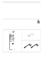
"Troubleshooting" YAMAHA and the Electronic Industries Association's Consumer Electronics Group recommend you to avoid prolonged exposure from excessive volume levels. SUPPLIED ACCESSORIES After unpacking, check that the following parts are contained. Batteries (size AA, LR6, AM-3) Remote Control - Yamaha DSP-E200 | Owner's Manual - Page 4
E200 -an extremely sophisticated audio component. The Digital Sound Field Processor (DSP) built in this unit takes full advantage of Yamaha's undisputed leadership in the field of digital audio processing to bring you a whole new world of listening experiences. Follow the instructions in this manual - Yamaha DSP-E200 | Owner's Manual - Page 5
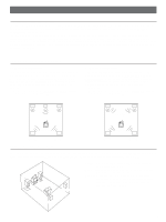
necessary as well as the rear speakers. If the digital sound field program is in the DOLBY PRO LOGIC or ENHANCED, conversations will be output from the center to the page 11.) Front L Front R Dialogue Dialogue Surround sound Surround sound Rear L Rear R Rear L Rear R SPEAKER PLACEMENT The - Yamaha DSP-E200 | Owner's Manual - Page 6
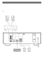
to the owner's manual for each component to be connected to this unit. • Choose one of the following three ways to connect this unit to your amplifier. A Connecting to an Integrated Amplifier or Stereo Receiver with PRE OUT and MAIN IN terminals Front speakers Left Right Integrated amp. MAIN IN - Yamaha DSP-E200 | Owner's Manual - Page 7
B Connecting to an Integrated Amplifier or Stereo Receiver that does not have PRE OUT and MAIN IN terminals If your amplifier or receiver has the REC OUT selector which is independent of the input selector, connect this unit to the amplifier or receiver tape REC OUT and auxiliary (AUX) input - Yamaha DSP-E200 | Owner's Manual - Page 8
C Connecting to a Control Amplifier and Power Amplifier Front speakers Left Right Power amp. INPUT SPEAKERS INPUT TAPE PB TAPE REC OUT MAIN OUT CENTER CENTER OUT REAR Control amp. PRE OUT (U.S.A. model) AC OUTLET UNSWITCHED 120V 60Hz 200W MAX. 1.6A MAX. Right Left Center speaker - Yamaha DSP-E200 | Owner's Manual - Page 9
when you use the built-in amplifier. However, if you drive a center speaker with an external power amplifier, connect input terminal of the external amplifier to this terminal. If you use the built-in amplifier and the external power amplifier at the same time, the sound will be output through both - Yamaha DSP-E200 | Owner's Manual - Page 10
IDENTIFICATION OF CONTROLS NATURAL SOUND DIGITAL SOUND FIELD PROCESSOR DSP-E200 POWER DELAY TEST ms NORMAL WIDE F C R PHANTOM PRO LOGIC CONCERT MONO ROCK CONCERT ENHANCED VIDEO MOVIE CONCERT HALL TAPE MONITOR DOLBY SURROUND PRO • LOGIC CENTER TEST MODE DIGITAL SOUND FIELD PROCESSING - Yamaha DSP-E200 | Owner's Manual - Page 11
position with the remote control transmitter. Otherwise, the result may not be satisfactory. 2 31 54 1 VOLUME 0 - dB ∞ Set to the " " position. 2 Set on the POWER of this unit and the amplifier etc. POWER 3 DIGITAL SOUND FIELD PROCESSING CONCERT MONO ROCK CONCERT PRO LOGIC ENHANCED VIDEO - Yamaha DSP-E200 | Owner's Manual - Page 12
the remote control transmitter. DELAY TEST ms NORMAL WIDE F C R PHANTOM PRO LOGIC CONCERT MONO ROCK CONCERT ENHANCED VIDEO MOVIE CONCERT HALL control(s) on the integrated amplifier or power amplifier to achieve proper balance. q In step 7, if the center mode is in the "PHANTOM", the sound - Yamaha DSP-E200 | Owner's Manual - Page 13
, when the digital sound field program is in the DOLBY PRO LOGIC or ENHANCED, the built-in automatic input balance control functions. This presents you the best surround condition without adjusting it manually. DESCRIPTION OF EACH SOUND FIELD PROGRAM PROGRAM PRO LOGIC ENHANCED CONCERT VIDEO - Yamaha DSP-E200 | Owner's Manual - Page 14
program suitable for the source. CENTER TEST MODE DIGITAL SOUND FIELD PROCESSING CONCERT MONO ROCK CONCERT PRO LOGIC ENHANCED VIDEO MOVIE CONCERT HALL OFF DOLBY SUR. PRO LOGIC 3 Select a source using the input selector on the integrated amplifier etc. * To select a tape deck connected to - Yamaha DSP-E200 | Owner's Manual - Page 15
while you are using this unit's Dolby Pro Logic Surround decoding function. q When this unit is in the Dolby Pro Logic Surround mode, if the main-source sound is considerably altered by overadjustment of the BASS or TREBLE controls on the integrated amplifier etc., the relationship with the center - Yamaha DSP-E200 | Owner's Manual - Page 16
keys do not function. q Once the output level is adjusted, the level value will be common among all the digital sound field programs except the DOLBY PRO LOGIC . q If any digital sound field program is not used, the FRONT EFFECT LEVEL keys do not function. Adjustment of the CENTER LEVEL If desired - Yamaha DSP-E200 | Owner's Manual - Page 17
strong lighting (especially an inverter type of fluorescent lamp etc.), it might cause the remote control transmitter not to work correctly. In this case, reposition the main unit to avoid direct lighting. SPECIFICATIONS Minimum RMS Output Power per Channel Center (8 ohms, 20 Hz - 20 kHz, 0.08% THD - Yamaha DSP-E200 | Owner's Manual - Page 18
the DOLBY PRO LOGIC or ENHANCED. The center sound output level is set to 0. The center mode is in the PHANTOM. Incorrect sound field program selection. No sound field program is selected. Direct sunlight or lighting (of an inverter type of flourescent lamp etc.) is striking the remote control sensor - Yamaha DSP-E200 | Owner's Manual - Page 19
ELECTRONIQUE FRANCE S.A. RUE AMBROISE CROIZAT BP70 CROISSY-BEAUBOURG 77312 MARNE-LA-VALLEE CEDEX02, FRANCE YAMAHA ELECTRONICS (UK) LTD. YAMAHA HOUSE, 200 RICKMANSWORTH ROAD WATFORD, HERTS WD1 7JS, ENGLAND YAMAHA SCANDINAVIA A.B. J A WETTERGRENS GATA 1, BOX 30053, 400 43 VÄSTRA FRÖLUNDA, SWEDEN
-
 1
1 -
 2
2 -
 3
3 -
 4
4 -
 5
5 -
 6
6 -
 7
7 -
8
-
9
-
10
-
11
-
12
-
13
-
14
-
15
-
16
-
17
-
18
-
19
 |
 |
Natural Sound Digital Sound Field Processor
4 Programs for Digital Sound Field Processing
2 Programs for Dolby Surround (DOLBY PRO LOGIC and ENHANCED)
Center and Rear Channel Power Amplifier
25W (8
Ω
) RMS Output Power, 0.08% THD, 20-20,000 Hz (Center)
25W + 25W (8
Ω
) RMS Output Power, 0.3% THD, 1,000 Hz (Rear)
Automatic Input Balance Control for Dolby Surround
Test Tone Generator for Easier Speaker Output Balance Adjustment
3 Center Channel Modes
Remote Control Capabilit
y
OWNER’S MANUAL
Thank you for selecting this YAMAHA digital sound field processor.
CONTENTS
Safety Instructions
....................................
2
Warning
...................................................
3
Supplied Accessories
..............................
3
Profile of This Unit
...................................
4
Speaker Configurations for This Unit
......
5
Connections
............................................
6
Identification of Controls
.........................
10
Adjustment Before Operation
.................
11
Using Digital Sound Field Processor
(DSP)
......................................................
13
Notes about the Remote Control
Transmitter
.............................................
17
Specifications
.........................................
17
Troubleshooting
......................................
18
IMPORTANT!
Please record the serial number of this
unit in the space below.
Model:
Serial No.:
The serial number is located on the rear
of the unit.
Retain this Owner’s Manual in a safe
place for future reference.
WARNING
TO REDUCE THE RISK OF FIRE OR
ELECTRIC SHOCK, DO NOT EXPOSE
THIS UNIT TO RAIN OR MOISTURE.
RISK OF ELECTRIC SHOCK
DO NOT OPEN
CAUTION:
TO REDUCE THE RISK OF
ELECTRIC SHOCK, DO NOT REMOVE
COVER (OR BACK), NO USER-SERVICEABLE
PARTS INSIDE, REFER SERVICING TO
QUALIFIED SERVICE PERSONNEL.
The lightning flash with arrowhead
symbol, within an equilateral triangle,
is intended to alert you to the
presence of uninsulated “dangerous
voltage” within the product’s
enclosure that may be of sufficient
magnitude to constitute a risk of
electric shock to persons.
The exclamation point within an
equilateral triangle is intended to alert
you to the presence of important
operating and maintenance
(servicing)
instructions in the
literature accompanying the
appliance.
•
Explanation of Graphical Symbols
CAUTION
DSP-E200