Yamaha MDX-E300 Owner's Manual - Page 10
Connecting your audio system, Digital connections, Analog connections
 |
View all Yamaha MDX-E300 manuals
Add to My Manuals
Save this manual to your list of manuals |
Page 10 highlights
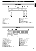
GETTING STARTED Connecting your audio system Digital connections This unit (MDX-E300) CD player (etc.) with optical OUT ANALOG SYSTEM IN D L C OUT CONNECTOR 1 DIGITAL OPTICAL 2 OUT IN R To AC outlet Amplifier/Receiver with optical IN/OUT DIGITAL OUT OPTICAL Optical cable Optical cable Optical cable DIGITAL IN DIGITAL OUT OPTICAL OPTICAL Notes for digital connections • The DIGITAL OPTICAL IN jacks can be connected to any component with an optical output so you can make direct digital recordings. • The DIGITAL OPTICAL OUT jacks can be connected to any component with an optical input so you can output digital audio from an MD. • Before making OPTICAL connections, remove the jack cover(s). • In order to protect the jacks from dust, be sure to attach the jack covers when the optical jacks are not being used. Analog connections Audio pin cables MD/TAPE This unit (MDX-E300) ANALOG SYSTEM IN D L C OUT CONNECTOR 1 DIGITAL OPTICAL 2 OUT IN R To AC outlet Amplifier/Receiver Notes for analog connections • The white plug on the audio pin cables corresponds to the L (left) channel and the red plug corresponds to the R (right) channel. Be sure to connect L (left) to L and R (right) to R. Also make sure that the plugs are fully inserted and that the connection is firm. • The ANALOG OUT jacks on this unit should be connected to the MD PLAY jacks on your amplifier. The ANALOG IN jacks on this unit should be connected to the MD REC jacks on your amplifier. 8
-
 1
1 -
2
-
3
-
4
-
 5
5 -
 6
6 -
 7
7 -
 8
8 -
 9
9 -
 10
10 -
 11
11 -
 12
12 -
 13
13 -
 14
14 -
 15
15 -
16
-
17
-
18
-
19
-
20
-
21
-
22
-
23
-
24
-
25
-
26
-
27
-
28
 |
 |
