Yamaha MDX-M5 Owner's Manual - Page 10
GETTING STARTED, Connecting the unit to the CRX-M5
 |
View all Yamaha MDX-M5 manuals
Add to My Manuals
Save this manual to your list of manuals |
Page 10 highlights
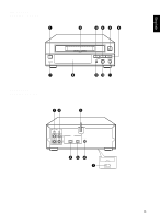
GETTING STARTED Connecting the unit to the CRX-M5 Never plug the AC power cord into the wall outlet until all other connections are completed. Follow the steps below to connect to the CRX-M5 using the supplied cords and accessories. 4 LINE LINE 1 2 OUT IN CD L DIGITAL OPTICAL R IN OUT SYSTEM CONNECTOR 3 1 Connect C to C, and D to D using the audio connecting cords. Insert the plugs into jacks of the same color. • The two audio connecting cords are the same, so you can connect C or D using either cord. • The white plug of the audio connecting cord corresponds to the left channel and the red plug corresponds to the right channel. Make sure that the left and right channel connections are properly made, and that the plugs are inserted firmly. 2 Connect the OPTICAL DIGITAL IN jack of the unit and the DIGITAL OUT jack on the CRX-M5 with the optical fiber cable. 3 Connect the unit and the CRX-M5 with the system cable. 4 Connect the AC power cord to a wall outlet. 1 AUX/MD TAPE C IN D OUT A IN B OUT L L R R SPEAKERS 6 MIN. /SPEAKER 6 MIN. /HAUT-PARLEUR +R- - L+ SUBWOOFER OUT FM 75 UNBAL GND AM ANTENNA DIGITAL OUT SYSTEM CONNECTOR CD TAPE OPTICAL MD 23 E-4
-
 1
1 -
2
-
3
-
4
-
 5
5 -
 6
6 -
 7
7 -
 8
8 -
 9
9 -
 10
10 -
 11
11 -
 12
12 -
 13
13 -
 14
14 -
 15
15 -
16
-
17
-
18
-
19
-
20
-
21
-
22
-
23
-
24
-
25
-
26
-
27
-
28
-
29
-
30
-
31
-
32
-
33
-
34
-
35
-
36
-
37
 |
 |
