Yamaha MG10 Owner's Manual - Page 4
Contents, Introduction, Features - 2 stereo mixer
 |
View all Yamaha MG10 manuals
Add to My Manuals
Save this manual to your list of manuals |
Page 4 highlights
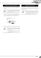
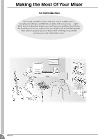
Introduction Thank you for your purchase of the YAMAHA MG10/2 mixing console. This mixing console combines ease of operation with support for multiple usage environments. Please read through this Owner's Manual carefully before beginning use, so that you will be able to take full advantage of this mixer's superlative features and enjoy trouble-free operation for years to come. Features G The MG10/2 provides ten input channels and mixes the signals into Stereo output. G The monitor includes a convenient C-R OUT jack. This jack can be used to monitor the main Stereo output, and the 2TR IN signals. G The mixer includes dual AUX SEND jacks and a single RETURN jack. The two independent AUX buses may be used as sends to external effectors and monitor systems. G Phantom power supply enables easy connection to condenser microphones that run on external power. G The mixer provides channel-specific INSERT I/O jacks for input channels 1 and 2. These jacks make it possible to insert different effectors into different channels. G Input channels 1 and 2 are each equipped with both an XLR mic input jack and a TRS phone-type line jack. Input channels 7/8 and 9/10 are each equipped with both a TRS line input jack and an RCA line input jack. This wide assortment of connectors enables connection to many different devices, from microphones to line-level devices to stereo-output synthesizers. G You can mount the mixer to a microphone stand using the optional BMS-10A adaptor. Contents Introduction 4 Features 4 Contents 4 Before Turning on the Mixer 5 Turning the Power On 5 Making the Most Of Your Mixer 6 1 A Place For Everything and Everything In Its Place 7 2 Where Your Signal Goes Once It's Inside the Box 10 3 The First Steps in Achieving Great Sound .... 11 4 External Effects and Monitor Mixes 13 5 Making Better Mixes 15 Front & Rear Panels 17 Channel Control Section 17 Master Control Section 18 Input/Output Section 19 Rear Section 20 Setting Up 21 Setup Procedure 21 Setup Examples 21 Mounting to a Microphone Stand 22 Appendix 23 Specifications 23 Dimensional Diagrams 25 Block Diagram and Level Diagram 26 4 MG10/2
-
 1
1 -
 2
2 -
 3
3 -
 4
4 -
 5
5 -
 6
6 -
 7
7 -
 8
8 -
 9
9 -
 10
10 -
11
-
12
-
13
-
14
-
15
-
16
-
17
-
18
-
19
-
20
-
21
-
22
-
23
-
24
-
25
-
26
-
27
-
28
 |
 |
