Yamaha MSP5 Owner's Manual - Page 4
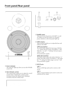
Front panel/Rear panel - used
 |
UPC - 086792856711
View all Yamaha MSP5 manuals
Add to My Manuals
Save this manual to your list of manuals |
Page 4 highlights
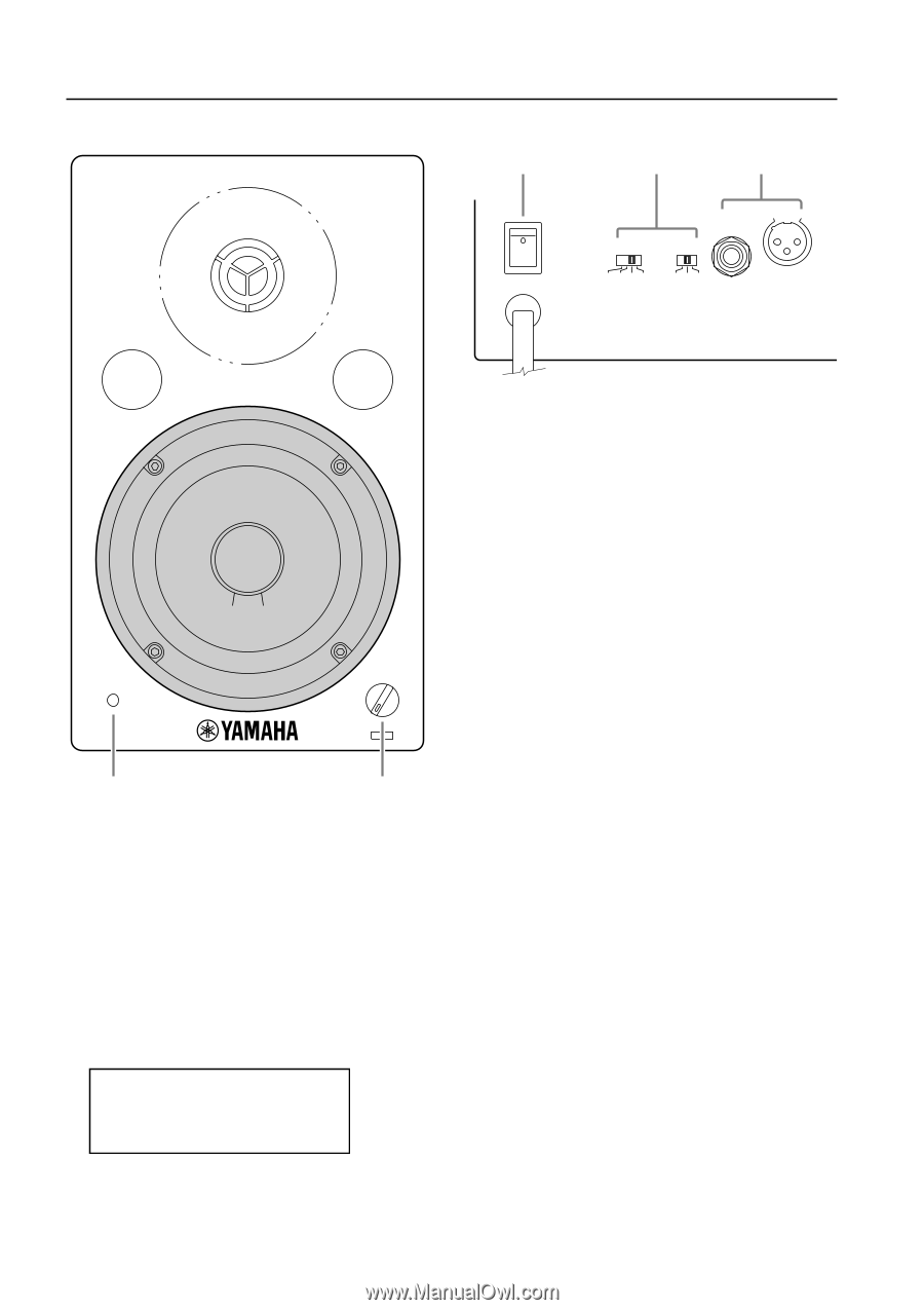
Front panel/Rear panel 3 4 5 ON OFF POWER NEUTRIK 2 1 3 -2 -1 0 +1 -1 0 +1 LOW HIGH TRIM LINE 2 LINE 1 INPUT VOL 1 2 1 Power indicator This indicator lights up when you turn the POWER switch ON. 2 VOL (Volume) control This control knob enables you to adjust the overall sound volume. Rotating the control counter clockwise lowers the volume level. Rotating it clockwise raises the volume level. CAUTION TO PREVENT ELECTRIC SHOCK, MATCH WIDE BLADE OF PLUG TO WIDE SLOT, FULLY INSERT. 3 POWER switch This switch turns the power to the MSP5 on and off. When you turn this switch on, the green power indicator on the front panel lights up. 4 TRIM switches These switches enable you to adjust the bass and treble for the MSP5. LOW: four positions The LOW switch adjusts the bass range. With the "+1" setting, the bass range is boosted by 1.5 dB. With the "-1" and "-2" settings, the bass range is cut by 1.5 dB. (See performance graph.) HIGH: three positions The HIGH switch adjusts the treble. With the "+1" setting, the treble range is boosted by 1.5 dB. With the "-1" setting, the treble range is cut by 1.5 dB. (See performance graph.) 5 INPUT jacks LINE 1 This is an XLR-type jack used to connect a balanced. LINE 2 This is a monaural phone jack used to connect an unbalanced line output. 4
-
 1
1 -
 2
2 -
 3
3 -
 4
4 -
 5
5 -
 6
6 -
 7
7 -
 8
8 -
 9
9 -
 10
10 -
11
-
12
-
13
-
14
-
15
-
16
 |
 |