Yamaha N-100 Owner's Manual - Page 26
Keyboard Stand Assembly
 |
View all Yamaha N-100 manuals
Add to My Manuals
Save this manual to your list of manuals |
Page 26 highlights
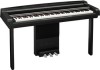
ENGLISH Keyboard Stand Assembly Keyboard Stand Assembly CAUTION • Be careful not to confuse parts, and be sure to install all parts in the correct direction. Please assemble the unit in the appropriate sequence. • Assembly should be carried out by at least two persons. • Be sure to use the included screws only, and insert screws of the correct size in the correct hole locations. Do not use any other screws. Use of incorrect screws can cause damage or malfunction of the product. • Be sure to tighten all screws upon completing assembly of each unit. • To disassemble, reverse the assembly sequence. Have a Phillips-head (+) screwdriver ready. Remove all parts from the box. Confirm that all parts shown in the illustration are provided. A D Front leg Pedal cord C Pedal box AC power cord (The shape of plug differs depending on locale.) B Speaker box D Front leg 6 x 20 mm long screws x4 6 x 16 mm short screws x12 • Before starting installation, remove the vinyl ties that bundle the pedal cord and AC power cord. 1. Lean A against the wall. 1-1 Spread a large soft cloth such as a blanket on the floor in front of the wall. 1-2 Lay A on the soft cloth with its keyboard side fac- ing toward you. A 26 N-100 Owner's Manual
-
 1
1 -
2
-
3
-
4
-
5
-
6
-
7
-
8
-
9
-
10
-
11
-
12
-
13
-
14
-
15
-
16
-
17
-
18
-
19
-
20
-
 21
21 -
 22
22 -
 23
23 -
 24
24 -
 25
25 -
 26
26 -
 27
27 -
 28
28 -
 29
29 -
 30
30 -
 31
31 -
32
-
33
-
34
-
35
-
36
-
37
-
38
-
39
-
40
-
41
-
42
 |
 |
