Yamaha P3200 Owner's Manual
Yamaha P3200 Manual
 |
View all Yamaha P3200 manuals
Add to My Manuals
Save this manual to your list of manuals |
Yamaha P3200 manual content summary:
- Yamaha P3200 | Owner's Manual - Page 1
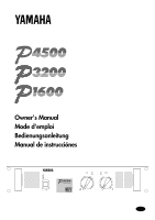
POWER AMPLIFIER Owner's Manual Mode d'emploi Bedienungsanleitung Manual de instrucciónes TEMP PROTECTION POWER ON OFF EEEngine A 20 15 CLIP B SIGNAL 20 15 25 10 25 10 30 40 ∞ 30 6 3 40 0 -dB ∞ 6 3 0 M - Yamaha P3200 | Owner's Manual - Page 2
you for purchasing a Yamaha P4500/3200/1600 series power amplifier. This series of audio amps was developed from Yamaha's wealth of experience in building PA equipment and its tradition of careful attention to every detail of circuit design. These amps feature high power and superb quality together - Yamaha P3200 | Owner's Manual - Page 3
five or more amps, or when (even with four or fewer units) the back of the rack cannot be left open .......... 6 Portable Rack Mounting 7 Positioning the Housed Amplifier 7 Specifications 8 General Specifications 8 Block Diagram 9 Dimensions 9 Performance Graphs 10 Troubleshooting 10 - Yamaha P3200 | Owner's Manual - Page 4
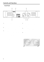
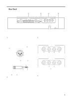
25 10 25 10 30 40 ∞ 30 6 3 40 0 -dB ∞ 6 3 0 56 1 POWER switch and indicator This is the main POWER switch. Press to power ON the amplifier. Press again to power OFF. The POWER indicator lights up when the amplifier is powered ON. 2 TEMP indicator When the temperature of the heat sink - Yamaha P3200 | Owner's Manual - Page 5
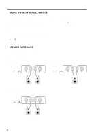
SPEAKERS terminals For polarity in each mode, refer to the following diagram. • STEREO, PARALLEL mode SPEAKERS CHANNEL B CHANNEL A Hot 21 Ground 3 and Ground (G). 2 STEREO/BRIDGE/PARALLEL switch This slide switch is used to set the amplifier operating mode: STEREO, BRIDGE or PARALLEL. For - Yamaha P3200 | Owner's Manual - Page 6
, channels A and B operate independently (as a conventional stereo amp). The CHANNEL A input signal will be output from the front panel (channel) A volume control to adjust the volume. s SPEAKER IMPEDANCE In STEREO and PARALLEL modes, the minimum load (=speaker) impedance is 4Ω. In BRIDGE mode it - Yamaha P3200 | Owner's Manual - Page 7
speaker porality. • Speaker fuse The output capacity of your amplifier is very high: 460 W+460 W (8Ω) in stereo and 1240 W (8Ω) in monaural on the P4500; 340 W+340 W (8Ω) in stereo and 880 W (8Ω) in monaural on the P3200; 160 W+160 W (8Ω) in stereo and 400 W (8Ω) in monaural on the P1600. Be sure - Yamaha P3200 | Owner's Manual - Page 8
s Mounting in an EIA standard rack If multiple high-power amp units are mounted in a rack with poor ventilation, the heat from the amps will cause the interior of the amp to become very hot, causing the performance of the amps to be impaired. When mounting amps in a rack, you must make provision for - Yamaha P3200 | Owner's Manual - Page 9
CHANNEL B CHANNEL A G G (BRIDGE) (PARALLEL) BRIDGE SPEAKERS CHANNEL B CHANNEL A STEREO PARALLEL STEREO BRIDGE MAX. OUTPUT 450W/4Ω (STEREO) MAX. OUTPUT 900W/8Ω (BRIDGE) (STEREO) 4-8Ω/SP (BRIDGE) 8-16Ω/SP s Positioning the Housed Amplifier Place the case so that the ventilation airflow - Yamaha P3200 | Owner's Manual - Page 10
Specifications s General Specifications Power Output Level (Rated Power) 20 Hz~20 kHz 0.05% 8Ω/STEREO 4Ω/STEREO 8Ω/BRIDGE 1 kHz 0.05% 8Ω/STEREO 4Ω/STEREO 8Ω/BRIDGE 1 kHz, 20 ms, no clip 2Ω/STEREO Power Bandwidth Half Power, 0.1% Total Harmonic Distortion (THD + N) 4~8Ω/STEREO 20 Hz~20 kHz - Yamaha P3200 | Owner's Manual - Page 11
s Block Diagram CHANNEL A (BRIDGE) (PARALLEL) G INPUT G CHANNEL B s Dimensions Ach Power Amp SIGNAL A PC Limiter CHANNEL A CLIP Temperature Sensor (Heat Sink) Protection Circuit PROTECTION SPEAKERS TEMP PARALLEL BRIDGE B STEREO CLIP Bch Power Amp PC Limiter SIGNAL CHANNEL B 26 61.2 - Yamaha P3200 | Owner's Manual - Page 12
by the TEMP indicator. Check the amplifier ventilation conditions and take appropriate measures to improve airflow around the amplifier. The thermal protection circuit operates to protect the power transistors. Consult your dealer or nearest Yamaha service center. The relay operates to protect - Yamaha P3200 | Owner's Manual - Page 13
Yamaha P4500/3200/1600. Cette série d'amplificateurs audio est le fruit d'une longue expérience que Yamaha a accumulée en fabricant du matériel PA ainsi que d'une attention traditionnelle portée à tous les détails de la conception d'un circuit service technique agréé par Yamaha STEREO/ probleme 10 - Yamaha P3200 | Owner's Manual - Page 14
fois de plus sur cette touche pour le mettre hors tension. Le témoin POWER s'allume lorsque l'amplificateur est mis sous tension. 2 Témoin TEMP Ce témoin trop important. Une fois le problème résolu, le circuit de protection se désenclenche automatiquement et l'amplificateur reprend son - Yamaha P3200 | Owner's Manual - Page 15
(+) et le signal froid à la broche 3 (-). 3 Bornes SPEAKERS Pour la polarité à choisir en fonction du mode, veuillez consulter l'illustration suivante. • Mode STEREO, PARALLEL SPEAKERS CHANNEL B CHANNEL A Chaud 21 3 Masse Froid • Entrées jack TRS Le signal chaud est à la pointe (+), le froid - Yamaha P3200 | Owner's Manual - Page 16
du canal A est envoyé aux sorties BRIDGE. Dans ce cas, servez-vous de la commande de volume A . s Impedance des enceintes Pour les modes STEREO et PARALLEL, l'impédance minimale de charge (des enceintes) est de 4Ω, contre 8Ω pour le mode BRIDGE. N'utilisez que des enceintes satisfaisant à ces - Yamaha P3200 | Owner's Manual - Page 17
sur la polarité des enceintes. • Fusible des enceintes Votre amplificateur est très puissant: 460 W+460 W (8Ω) en stéréo et 1240 W (8Ω) en mono sur le P4500; 340 W+340 W (8Ω) en stéréo et 880 W (8Ω) en mono sur le P3200; 160 W+160 W (8Ω) en stéréo et 400 W (8Ω) en mono sur le P1600. Assurez - Yamaha P3200 | Owner's Manual - Page 18
une grille de ventilation en haut du rack. Grille de ventilation Yamaha propose une grille de ventilation de 1U (VP1, disponible en l'avant ou à l'arrière du rack) TEMP PROTECTION POWER ON OFF TEMP PROTECTION POWER ON OFF TEMP PROTECTION POWER ON OFF EEEngine A 20 15 CLIP B SIGNAL 20 15 - Yamaha P3200 | Owner's Manual - Page 19
tement ouverte INPUT CHANNEL B CHANNEL A G G (BRIDGE) (PARALLEL) BRIDGE SPEAKERS CHANNEL B CHANNEL A STEREO PARALLEL STEREO BRIDGE MAX. OUTPUT 450W/4Ω (STEREO) MAX. OUTPUT 900W/8Ω (BRIDGE) (STEREO) 4-8Ω/SP (BRIDGE) 8-16Ω/SP s Installation de l'amplificateur à tout autre endroit Disposez - Yamaha P3200 | Owner's Manual - Page 20
de tension 8Ω toute la bande de fréq STEREO BRIDGE Sensibilité (Vol. max.), niveau nominal à 8Ω Gain de tension (Vol. max.) Commandes Face avant Connecteurs Face arrière Entrées Indicateurs Circuits de protection Sorties POWER TEMP PROTECTION (Etouff.) CLIP OUTPUT SIGNAL Limiteur de - Yamaha P3200 | Owner's Manual - Page 21
s Schéma CHANNEL A (BRIDGE) (PARALLEL) G INPUT G CHANNEL B s Dimensions Ach Power Amp SIGNAL A PC Limiter CHANNEL A CLIP Temperature Sensor (Heat Sink) Protection Circuit PROTECTION SPEAKERS TEMP PARALLEL BRIDGE B STEREO CLIP Bch Power Amp PC Limiter SIGNAL CHANNEL B 26 61.2 292 379 - Yamaha P3200 | Owner's Manual - Page 22
les mesures nécessaire pour améliorer la circulation autour de l'amplificateur. Le circuit de protection thermique fonctionne pour protéger les transistors de puissance. Consulter votre distributeur ou centre de service Yamaha le plus proche. Le relais fonctionne pour protéger le système de - Yamaha P3200 | Owner's Manual - Page 23
sich für einen Yamaha P4500/3200/ 1600 Leistungsverstärker entschieden haben. Diese Endstufenserie beruht auf Yamahas reichhaltiger Erfahrung bei diese Endstufen nahtlos in jeden Installationstyp einfügen. • Drei Betriebsarten: STEREO-Betrieb, in dem Kanal A und B separat angetrieben werden, PARALLEL - Yamaha P3200 | Owner's Manual - Page 24
einzuschalten und noch einmal, um sie wieder auszuschalten. Die POWER-Diode leuchtet, sobald Sie den P4500/3200/1600 einschalten. 2 TEMP-Diode Diese Diode leuchtet Lautsprecherausgängen zurückzuführen ist. Sobald das betreffende Problem behoben ist, wird die Schutzschaltung wieder deaktiviert - die - Yamaha P3200 | Owner's Manual - Page 25
CHANNEL B CHANNEL A STEREO BRIDGE Im BRIDGE-Betrieb werden die (-) Buchsen von Kanal A und B nicht verwendet. Die Mindestimpedanz der verwendeten Lautsprecher entnehmen Sie bitte dem Abschnitt "Lautsprecherimpedanz" auf Seite 4. 4 GND-Anschluß Über diese Schraubklemme kann der P4500/3200/1600 - Yamaha P3200 | Owner's Manual - Page 26
Signal an den BRIDGE-Ausgängen an. In dem Fall ist nur noch der A -Lautstärkeregler (Kanal A) belegt. s Lautsprecherimpedanz Im STEREO- und PARALLEL-Betrieb beträgt die minimale Lastimpedanz (der Lautsprecher) 4Ω, im BRIDGE-Betrieb hingegen 8Ω. Verwenden Sie immer nur Lautsprecher, die diesen - Yamaha P3200 | Owner's Manual - Page 27
Anschließen der Lautsprecher 1. Schalten Sie die Endstufe aus (POWER). 2. Entfernen Sie die Schrauben der Blende(n) und nehmen sich sehen lassen: 460 W+460 W (8Ω) im Stereo-Betrieb und 1240 W (8Ω) im Bridge-Betrieb beim P4500; 340 W+340 W (8Ω) im Stereo-Betrieb und 880 W (8Ω) im BridgeBetrieb beim - Yamaha P3200 | Owner's Manual - Page 28
Sie auch ganz oben im Rack eine Lüftungsblende verwenden. Lüftungsblende Yamaha bietet eine 1U-Lüftungsblende (VP1, Sonderzubehör) an. 480 Einheit oder Rückseite des Racks anbringen). TEMP PROTECTION POWER ON OFF TEMP PROTECTION POWER ON OFF TEMP PROTECTION POWER ON OFF EEEngine A 20 15 CLIP B - Yamaha P3200 | Owner's Manual - Page 29
) Muß frei sein INPUT CHANNEL B CHANNEL A G G (BRIDGE) (PARALLEL) BRIDGE SPEAKERS CHANNEL B CHANNEL A STEREO PARALLEL STEREO BRIDGE MAX. OUTPUT 450W/4Ω (STEREO) MAX. OUTPUT 900W/8Ω (BRIDGE) (STEREO) 4-8Ω/SP (BRIDGE) 8-16Ω/SP s Festeinbau einer Endstufe Stellen Sie die Endstufe immer so - Yamaha P3200 | Owner's Manual - Page 30
Europa Andere Länder Leistungsaufnahme Abmessungen (B × H × T) Gewicht Zubehör Optionen P4500 460 W + 460 W 620 W + 620 W 1240 W 520 W dB 32,1 dB POWER Netzschalter (drücken=an, drücken=aus) Lautstärkeregler (31 Positionen, dB-kalibriert) Betriebswahlschalter (STEREO/BRIDGE/PARALLEL) Anschlu - Yamaha P3200 | Owner's Manual - Page 31
CHANNEL A (BRIDGE) (PARALLEL) G INPUT G CHANNEL B s Abmessungen Ach Power Amp SIGNAL A PC Limiter CHANNEL A CLIP Temperature Sensor (Heat Sink) Protection Circuit PROTECTION SPEAKERS TEMP PARALLEL BRIDGE B STEREO CLIP Bch Power Amp PC Limiter SIGNAL CHANNEL B 26 61.2 292 4.4 T:455 - Yamaha P3200 | Owner's Manual - Page 32
P4500 5k 1k Mode:STEREO Both ch Driven RL=4Ω, f=1kHz P3200 5k 1k Mode:STEREO Both ch Driven RL=4Ω, f=1kHz Power Consumption [W] Power Consumption [W] 100 20 1 P1600 5k 10 100 1k Output Power [W] Mode:STEREO Both ch Driven RL=4Ω, f=1kHz 1k 100 20 1 10 100 1k Output Power [W] Power - Yamaha P3200 | Owner's Manual - Page 33
Manual de instrucciónes ESPAÑOL Muchas gracias por la adquisición de este amplificador de la serie P4500/3200/1600 Yamaha. Esta serie de amplificadores de audio fue desarrollada con la rica experiencia de Yamaha en bastidor. • Tres modos de operación: modo STEREO (estéreo) en el que los canales - Yamaha P3200 | Owner's Manual - Page 34
20 15 CLIP B SIGNAL 20 15 25 10 25 10 30 40 ∞ 30 6 3 40 0 -dB ∞ 6 3 0 56 1 Interruptor e indicador de alimentación (POWER) Éste es el interruptor de alimentación principal. Presiónelo para conectar la alimentación del amplificador. Vuelva a presionarlo para desconectarla. Cuando - Yamaha P3200 | Owner's Manual - Page 35
a la polaridad en cada modo, consulte el diagrama siguiente. • Modo estéreo, paralelo SPEAKERS CHANNEL B CHANNEL A STEREO BRIDGE • Modo en puente SPEAKERS CHANNEL B CHANNEL A STEREO BRIDGE En el modo en puente (BRIDGE), las tomas (-) de los canales A y B (CHANNEL A y B) no se utilizan - Yamaha P3200 | Owner's Manual - Page 36
La toma de entrada de CHANNEL B no se utiliza. Los volúmenes de los canales A y # podrán ajustarse independientemente. s Impedancia de los altavoces En los modos STEREO y PARALLEL, la carga mínima (de los altavoces) es de 4Ω. En el modo BRIDGE es de 8Ω. Cerciórese de que la impedancia no caiga por - Yamaha P3200 | Owner's Manual - Page 37
para la conexión de los altavoces 1. Ponga el interruptor POWER en OFF. 2. Extraiga el (los) tornillo(s) de salida de su amplificador es muy alta: 460 W + 460 W (8Ω) en estéreo y 1240 W (8Ω) en monoaural en el P4500, 340 W + 340 W (8Ω) en estéreo y 880 W (8Ω) en monoaural en el P3200, y 160 W + 160 - Yamaha P3200 | Owner's Manual - Page 38
superficie superior del bastidor posee aberturas de ventilación. Panel de ventilación Yamaha proporciona un panel de ventilación VP1 de tamaño IU opcional. a la parte frontal o a la posterior del bastidor) TEMP PROTECTION POWER ON OFF TEMP PROTECTION POWER ON OFF TEMP PROTECTION POWER ON OFF - Yamaha P3200 | Owner's Manual - Page 39
PARALLEL STEREO BRIDGE MAX. OUTPUT 450W/4Ω (STEREO) MAX. OUTPUT 900W/8Ω (BRIDGE) (STEREO) 4-8Ω/SP (BRIDGE) 8-16Ω/SP s Ubicación del amplificador alojado Coloque la caja de forma que las vías de flujo del aire de ventilación no queden bloqueadas. Parte frontal NO Menos de 10 cm Parte frontal - Yamaha P3200 | Owner's Manual - Page 40
Unidos y Canadá Europa Otros Consumo Dimensiones (An × Al × Prf) Peso Accesorio Opciones P4500 460 W + 460 W 620 W + 620 W 1240 W 520 W + 520 de alimentación [POWER (ON/OFF)], Silenciamiento, Detección de DC Volumen (31 posiciones, calibrado en dB) Selector de modo (STEREO/BRIDGE/PARALLEL) - Yamaha P3200 | Owner's Manual - Page 41
en bloques A CHANNEL A (BRIDGE) (PARALLEL) G INPUT G Ach Power Amp PC Limiter SIGNAL CHANNEL A CLIP Temperature Sensor (Heat Sink) Protection Circuit PROTECTION SPEAKERS TEMP CHANNEL B PARALLEL BRIDGE B STEREO CLIP Bch Power Amp PC Limiter SIGNAL CHANNEL B s Dimensiones 26 61.2 292 - Yamaha P3200 | Owner's Manual - Page 42
P4500 5k Mode:STEREO Both ch Driven RL=4Ω, f=1kHz 1k P3200 5k 1k Mode:STEREO Both ch Driven RL=4Ω, f=1kHz Power Consumption [W] Power Consumption [W] 100 20 1 P1600 5k 10 100 1k Output Power [W] Mode:STEREO proteger los transistores de potencia. para proteger los transistores de potencia.
-
 1
1 -
 2
2 -
 3
3 -
 4
4 -
 5
5 -
 6
6 -
 7
7 -
8
-
9
-
10
-
11
-
12
-
13
-
14
-
15
-
16
-
17
-
18
-
19
-
20
-
21
-
22
-
23
-
24
-
25
-
26
-
27
-
28
-
29
-
30
-
31
-
32
-
33
-
34
-
35
-
36
-
37
-
38
-
39
-
40
-
41
-
42
 |
 |
POWER AMPLIFIER
Owner's Manual
Mode d'emploi
Bedienungsanleitung
Manual de instrucciónes
TEMP
PROTECTION
POWER
ON
OFF
A
B
CLIP
SIGNAL
–dB
∞
0
∞
0
40
30
20
15
10
3
6
25
40
30
20
15
10
3
6
25
EEEngine
M