Yamaha P3200 Owner's Manual - Page 6
Modes: Stereo/parallel/bridge, Speaker Impedance
 |
View all Yamaha P3200 manuals
Add to My Manuals
Save this manual to your list of manuals |
Page 6 highlights
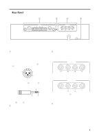
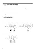
s Modes: STEREO/PARALLEL/BRIDGE STEREO mode In this mode, channels A and B operate independently (as a conventional stereo amp). The CHANNEL A input signal will be output from the CHANNEL A output jacks, and the CHANNEL B input signal will be output from the CHANNEL B output jacks. PARALLEL mode In this mode, the CHANNEL A input signal will be output from the output jacks of both channels A and B. The CHANNEL B input jack is not used. The (channel) A and # volumes can be adjusted independently. BRIDGE mode In this mode, the CHANNEL A input signal will be output from the BRIDGE output jacks. In this case, use the front panel (channel) A volume control to adjust the volume. s SPEAKER IMPEDANCE In STEREO and PARALLEL modes, the minimum load (=speaker) impedance is 4Ω. In BRIDGE mode it is 8Ω. Make sure that the impedance does not fall below this specified impedance. STEREO mode connections BRIDGE mode connections Set to STEREO BRIDGE STEREO PARALLEL SPEAKERS CHANNEL B CHANNEL A STEREO BRIDGE MAX. OUTPUT 450W/4Ω (STEREO) MAX. OUTPUT 900W/8Ω (BRIDGE) -+ Set to BRIDGE BRIDGE STEREO PARALLEL SPEAKERS CHANNEL B CHANNEL A STEREO BRIDGE MAX. OUTPUT 450W/4Ω (STEREO) MAX. OUTPUT 900W/8Ω (BRIDGE) -+ -+ -+ 4Ω min. 4Ω min. Speaker System PARALLEL mode connections BRIDGE Set to PARALLEL STEREO PARALLEL SPEAKERS CHANNEL B CHANNEL A STEREO BRIDGE MAX. OUTPUT 450W/4Ω (STEREO) MAX. OUTPUT 900W/8Ω (BRIDGE) -+ 8Ω min. Speaker System 4Ω min. 4Ω min. Speaker System 4
-
 1
1 -
 2
2 -
 3
3 -
 4
4 -
 5
5 -
 6
6 -
 7
7 -
 8
8 -
 9
9 -
 10
10 -
 11
11 -
 12
12 -
13
-
14
-
15
-
16
-
17
-
18
-
19
-
20
-
21
-
22
-
23
-
24
-
25
-
26
-
27
-
28
-
29
-
30
-
31
-
32
-
33
-
34
-
35
-
36
-
37
-
38
-
39
-
40
-
41
-
42
 |
 |
