Yamaha PM5000 Owner's Manual - Page 15
Input Channel Mono and Stereo Input Modules, Head Amp Block - meter
 |
View all Yamaha PM5000 manuals
Add to My Manuals
Save this manual to your list of manuals |
Page 15 highlights
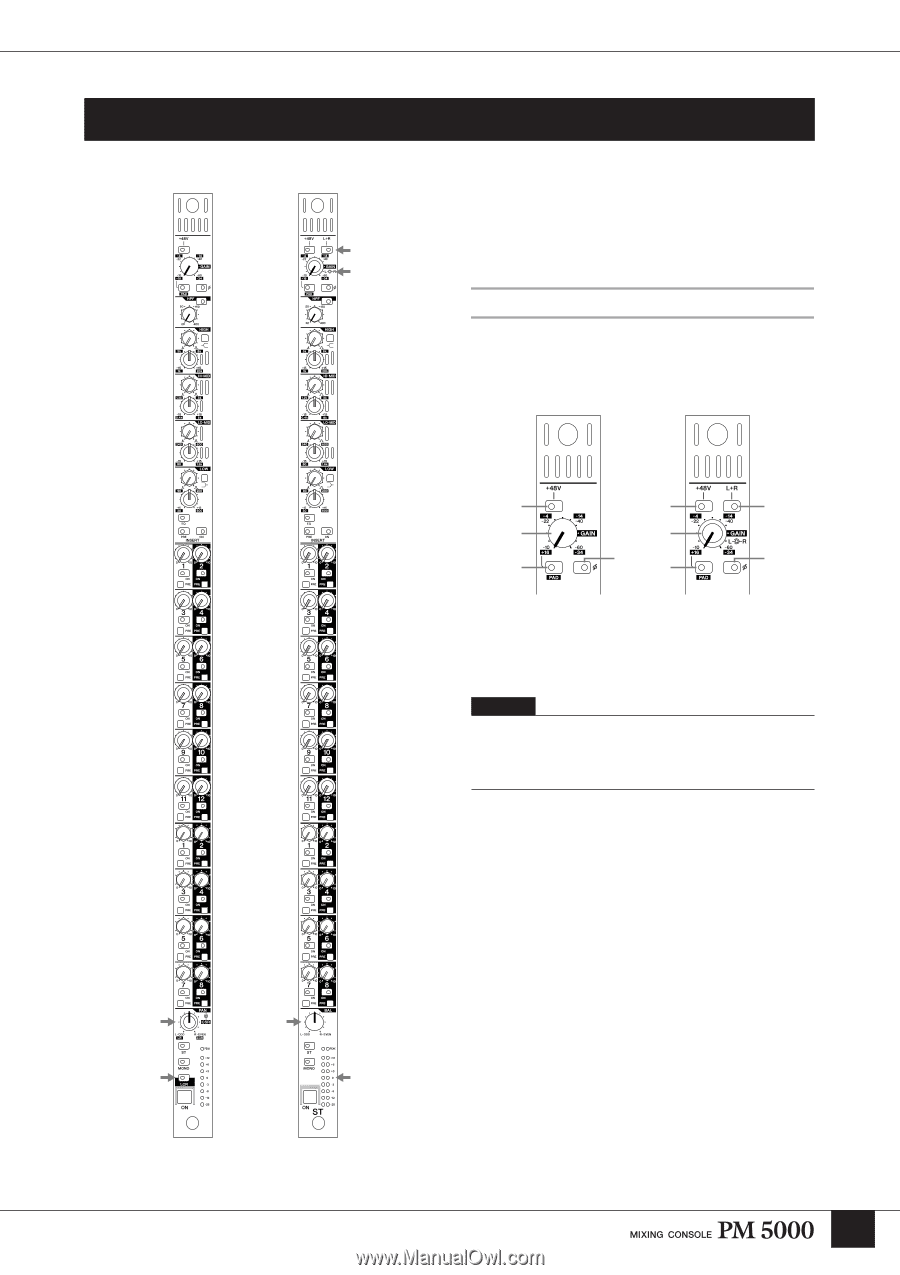
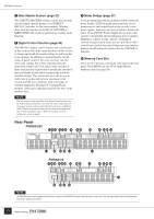
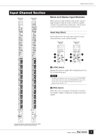
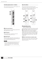
Input Channel Section Input Channel Section Mono Input Module Stereo Input Module Mono and Stereo Input Modules Mono and stereo input modules make up the console's input channel section. In essence each stereo module contains two parallel mono signal paths, and the panel controls control both channels simultaneously. Head Amp Block Initial adjustment of the input audio signal level and other parameters can be carried out here. Mono Input Module Stereo Input Module 1 1 4 3 3 2 52 5 1 [+48V] Switch Engage this switch to supply +40-volt phantom power to the corresponding input. NOTE In order to use phantom power, the rear-panel [+48V MASTER] switch must be turned on. The [+48V MASTER ON] indicator on the left side of the meter bridge will light when the master phantom power switch is on. 2 [PAD] Switch When this switch is engaged a 26-db pad is inserted at the channel's input to compensate for high-level source signals. The arrows indicate controls and indicators that differ between the mono and stereo input modules. 15
-
 1
1 -
2
-
3
-
4
-
5
-
6
-
7
-
8
-
9
-
 10
10 -
 11
11 -
 12
12 -
 13
13 -
 14
14 -
 15
15 -
 16
16 -
 17
17 -
 18
18 -
 19
19 -
 20
20 -
21
-
22
-
23
-
24
-
25
-
26
-
27
-
28
-
29
-
30
-
31
-
32
-
33
-
34
-
35
-
36
-
37
-
38
-
39
-
40
-
41
-
42
-
43
-
44
-
45
-
46
-
47
-
48
-
49
-
50
-
51
-
52
-
53
-
54
-
55
-
56
-
57
-
58
-
59
-
60
-
61
-
62
-
63
-
64
-
65
-
66
-
67
-
68
-
69
-
70
-
71
-
72
-
73
-
74
-
75
-
76
-
77
-
78
-
79
-
80
-
81
-
82
-
83
-
84
-
85
-
86
-
87
-
88
-
89
-
90
-
91
-
92
-
93
-
94
-
95
-
96
-
97
-
98
-
99
-
100
-
101
-
102
-
103
-
104
-
105
-
106
 |
 |