Yamaha RX-V670 Owner's Manual
Yamaha RX-V670 Manual
 |
View all Yamaha RX-V670 manuals
Add to My Manuals
Save this manual to your list of manuals |
Yamaha RX-V670 manual content summary:
- Yamaha RX-V670 | Owner's Manual - Page 1
RX-V670 Natural Sound Stereo Receiver 5 Speaker Configuration 70W +70W (8Ω) RMS Output Power, 0.03% THD, 20-20,000 Hz (Front) 70W (8Ω) RMS Output Power, 0.08% THD, 1 kHz (Center) 25W + 25W (8Ω) RMS Output Power, 0.3% THD, 1 kHz (Rear) Digital Sound Field Processor; 4 Programs for Digital Sound Field - Yamaha RX-V670 | Owner's Manual - Page 2
Servicing - The user should not attempt to service the unit beyond those means described in the operating instructions. All other servicing should be referred to qualified service Electrical Code, ANSI/NFPA 70, provides information with regard to proper grounding of the mast and supporting structure, - Yamaha RX-V670 | Owner's Manual - Page 3
storm. 9 Be sure to read the "Troubleshooting" section on common operating errors before concluding that the instructions found in the users manual, may and "ON", please try to eliminate the problem by using one of the following measures: sounds is often undetectable until it is too late, YAMAHA - Yamaha RX-V670 | Owner's Manual - Page 4
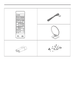
SUPPLIED ACCESSORIES After unpacking, check that the following parts are contained. q Remote Control Transmitter q Indoor FM Antenna q AM Loop Antenna q Batteries (size AA, LR6, UM-3) q User Program Sheets 4 - Yamaha RX-V670 | Owner's Manual - Page 5
stereo receiver -an extremely sophisticated audio component. The Digital Sound Field Processor (DSP) built into this unit takes full advantage of Yamaha's undisputed leadership in the field of digital audio processing to bring you a whole new world of listening experiences. Follow the instructions - Yamaha RX-V670 | Owner's Manual - Page 6
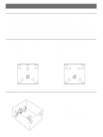
Dialogue Dialogue Surround sound Surround sound Rear L Rear R Rear L Rear R SPEAKER PLACEMENT The recommanded speaker configuration, the 5-speaker configuration, will require two speaker pairs: front speakers (your normal stereo speakers), and rear speakers, plus a center speaker. When you - Yamaha RX-V670 | Owner's Manual - Page 7
this unit. LD player Video cassette recorder 1 Rear speakers Center speaker Right Left Front speakers A Right Left AUDIO OUT VIDEO OUT AUDIO OUT AUDIO IN VIDEO OUT VIDEO IN Compact disc player OUTPUT Turntable GND OUTPUT (U.S.A. model) REMOTE CONTROL Tape deck 1 LINE OUT LINE IN To - Yamaha RX-V670 | Owner's Manual - Page 8
consumption of components) that can be connected to the SWITCHED AC OUTLETS is 100 watts (80 watts for Canada model). REMOTE CONTROL (PHONO) connector If you have a YAMAHA turntable with the terminal for remote control, connect it to this connector by using the cable provided with the turntable - Yamaha RX-V670 | Owner's Manual - Page 9
to a good grounding. A good grounding is a metal stake driven into moist earth. Notes q When connecting the indoor FM antenna, make sure that the grooved part of the connector hole is facing downward. q If you need an outdoor FM antenna to improve FM reception quality, either a 300-ohm feeder or - Yamaha RX-V670 | Owner's Manual - Page 10
at the listening position will be the same from each speaker. This is important for the best performance of the digital sound field processor. The adjustment of each speaker output level should be done at your listening position with the remote control transmitter. Otherwise, the result may not be - Yamaha RX-V670 | Owner's Manual - Page 11
Turn up the volume by using the remote control transmitter. You will hear a test tone (like pink noise) from the left front speaker, then the center speaker, then the right front speaker, and then the rear speakers, for about two seconds each. The display illumination changes as shown below. Front - Yamaha RX-V670 | Owner's Manual - Page 12
output level of the front speakers is used as the basis in speaker balance adjustment. q Once you have completed these adjustments, you can adjust whole sound level on your audio system by using the VOLUME control (or the MASTER VOLUME keys on the remote control transmitter). q If you use external - Yamaha RX-V670 | Owner's Manual - Page 13
Display 3 Tuner controls PHONES jack 4 To play a source 1 VOLUME 1, 6 7 7 If desired, adjust the BASS, TREBLE, BALANCE controls, etc. (refer to page 15) and use the digital sound speakers to be used. SPEAKERS * If you use two front speaker the video image from the VCR and the sound from the - Yamaha RX-V670 | Owner's Manual - Page 14
1, 4 2 To record a source to tape 1 Select the source to be recorded. 4 To monitor the audio and/or video signals being recorded, press the input selector button for the audio or video tape recorder being used to make the recording. * To dub from tape to tape, refer to the "Notes" shown below. * - Yamaha RX-V670 | Owner's Manual - Page 15
response. TREBLE : Turn this clockwise to increase (or counterclockwise to decrease) the high frequency response. Note These controls are effective only for the sound from the front speakers. When you listen with headphones Connect the headphones to the PHONES jack. You can listen to the main - Yamaha RX-V670 | Owner's Manual - Page 16
are weak), change to the MANUAL TUNING method. Display information 1 FM 16 MHz 0 40 60 80 100 STEREO 2 3 Œ Displays the band and frequency of the received station. Indicates the signal level of the received station. Ž Illuminates when an FM stereo broadcast with sufficient signal strength - Yamaha RX-V670 | Owner's Manual - Page 17
the desired page (A - E) of preset station buttons while watching the display. A/B/C/D/E PRESET FM MHz 3 MEMORY PRESET FM MEMORY MHz 4 Press a station frequency. PRESET FM MHz AUTO TUNING 0 40 60 80 100 STEREO Shows the displayed station has been programmed to A1. * In the same way, - Yamaha RX-V670 | Owner's Manual - Page 18
actual concert hall. This program is designed specifically to enhance mono source programs. Compared to a strictly mono setting, the sound image created in this mode is wider and slightly forward of the speaker pair, lending an immediacy to the overall sound. It is particularly effective when used - Yamaha RX-V670 | Owner's Manual - Page 19
center mode is in the PHANTOM, the front speakers output the sound of the center speaker. q If you connect an external amplifier to this unit, see if it has built-in surround sound or ambience circuitry. If it does, then be sure that the surround or ambience circuitry on that amplifier is off while - Yamaha RX-V670 | Owner's Manual - Page 20
and the output level of each speaker. (For details, refer to the corresponding descriptions on this page and the next page.) Note If you prefer to cancel the selected program, press the OFF switch. The sound will be the normal 2-channel stereo without surround sound effect. PRO LOGIC Adjustment of - Yamaha RX-V670 | Owner's Manual - Page 21
does not function. Adjustment of the REAR LEVEL If desired, you can adjust the sound output level of the rear speakers with this control even if the output level is already set in "Speaker balance adjustment" on page 10. REAR LEVEL R Illuminates Adjustable q By continuously pressing "+" or "-" on - Yamaha RX-V670 | Owner's Manual - Page 22
. Notes q The SLEEP timer can be controlled only with the remote control transmitter. q The components on which the SLEEP timer is effective 1 To cancel the selected SLEEP time Press once when the SLEEP time displays 30. Indicates the SLEEP time. SLEEP Flashes on and off continuously. Select - Yamaha RX-V670 | Owner's Manual - Page 23
YAMAHA components with this remote control transmitter, set the YPC-USER-LEARN switch to the YPC (Yamaha Preset Code) position. For Control of This Unit Refer to "YPC-USER preset station buttons. Used for speaker balance adjustment. Adjusts sound output level at each speaker. Refer to "RESET button" - Yamaha RX-V670 | Owner's Manual - Page 24
For Other Component Control Identify the remote control transmitter keys with your component's keys. If these keys are identical, their function will be the same. On each key function, refer to the corresponding instruction on your component's manual. Controls the compact disc player. * DISC SKIP - Yamaha RX-V670 | Owner's Manual - Page 25
used only for learning other remote control transmitter's functions. YPC-USER-LEARN switch (Refer to page 23.) YPC: Set to this position when using preset key functions (for controlling this unit and/or YAMAHA components). * "YPC" is the abbreviation of YAMAHA Preset Code. USER: Set to this position - Yamaha RX-V670 | Owner's Manual - Page 26
Learned Function 1 To Clear All Learned Functions 1 Set to "USER". 2 Press and hold the CLEAR button using the point of REMOTE CONTROL TRANSMITTER Battery installation Remote control transmitter operation range 2 13 Remote control sensor Battery replacement If you find that the remote control - Yamaha RX-V670 | Owner's Manual - Page 27
the power cord and contact your authorized YAMAHA dealer or service center for help. Amplifier SYMPTOM The unit fails to turn on when the POWER switch is pressed. No sound or no picture. The sound suddenly goes off. Only one side speaker outputs the sound. Sound "hums". The volume level is low - Yamaha RX-V670 | Owner's Manual - Page 28
1 SWITCHED OUTLET [Australia model 100W max. total Dimensions (W x H x D 435 x 151.3 x 296.7 mm (17-1/8" x 5-15/16" x 11-11/16") Weight 10.5 kg (23 lbs. 2 oz.) Accessories AM loop antenna Indoor FM antenna Remote control transmitter Batteries User program sheets Specifications are subject to - Yamaha RX-V670 | Owner's Manual - Page 29
BLOCK DIAGRAM 29 - Yamaha RX-V670 | Owner's Manual - Page 30
ELECTRONIQUE FRANCE S.A. RUE AMBROISE CROIZAT BP70 CROISSY-BEAUBOURG 77312 MARNE-LA-VALLEE CEDEX02, FRANCE YAMAHA ELECTRONICS (UK) LTD. YAMAHA HOUSE, 200 RICKMANSWORTH ROAD WATFORD, HERTS WD1 7JS, ENGLAND YAMAHA SCANDINAVIA A.B. J A WETTERGRENS GATA 1, BOX 30053, 400 43 VÄSTRA FRÖLUNDA, SWEDEN
-
 1
1 -
 2
2 -
 3
3 -
 4
4 -
 5
5 -
 6
6 -
 7
7 -
8
-
9
-
10
-
11
-
12
-
13
-
14
-
15
-
16
-
17
-
18
-
19
-
20
-
21
-
22
-
23
-
24
-
25
-
26
-
27
-
28
-
29
-
30
 |
 |
IMPORTANT!
Please record the serial number of this
unit in the space below.
Model:
Serial No.:
The serial number is located on the rear
of the unit.
Retain this Owner’s Manual in a safe
place for future reference.
WARNING
TO REDUCE THE RISK OF FIRE OR
ELECTRIC SHOCK, DO NOT EXPOSE
THIS UNIT TO RAIN OR MOISTURE.
RISK OF ELECTRIC SHOCK
DO NOT OPEN
CAUTION:
TO REDUCE THE RISK OF
ELECTRIC SHOCK, DO NOT REMOVE
COVER (OR BACK), NO USER-SERVICEABLE
PARTS INSIDE, REFER SERVICING TO
QUALIFIED SERVICE PERSONNEL.
The lightning flash with arrowhead
symbol, within an equilateral triangle,
is intended to alert you to the
presence of uninsulated “dangerous
voltage” within the product’s
enclosure that may be of sufficient
magnitude to constitute a risk of
electric shock to persons.
The exclamation point within an
equilateral triangle is intended to alert
you to the presence of important
operating and maintenance
(servicing)
instructions in the
literature accompanying the
appliance.
•
Explanation of Graphical Symbols
CAUTION
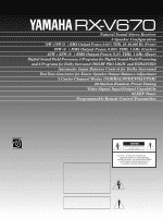
Natural Sound Stereo Receiver
5 Speaker Configuration
70W +70W (8
Ω
) RMS Output Power, 0.03% THD, 20–20,000 Hz (Front)
70W (8
Ω
) RMS Output Power, 0.08% THD, 1 kHz (Center)
25W + 25W (8
Ω
) RMS Output Power, 0.3% THD, 1 kHz (Rear)
Digital Sound Field Processor; 4 Programs for Digital Sound Field Processing
and 2 Programs for Dolby Surround (DOLBY PRO LOGIC and ENHANCED)
Automatic Input Balance Control for Dolby Surround
Test Tone Generator for Easier Speaker Output Balance Adjustment
3 Center Channel Modes (NORMAL/WIDE/PHANTOM)
40-Station Random Preset Tuning
Video Signal Input/Output Capability
SLEEP Timer
Programmable Remote Control Transmitter
RX-V670
Thank you for selecting this YAMAHA stereo receiver.
OWNER’S MANUAL
CONTENTS
Safety Instructions
................................
2
Supplied Accessories
.........................
4
Profile of This Unit
..............................
5
Speaker Setup for This Unit
...............
6
Connections
........................................
7
Adjustment Before
Operation
..........................................
10
Operations
........................................
13
Tuning Operations
............................
16
Using Digital Sound Field
Processor (DSP)
...............................
18
Setting the SLEEP Timer
..................
22
Remote Control Transmitter
.............
23
Notes about the Remote
Control Transmitter
...........................
26
Troubleshooting
................................
27
Specifications
...................................
28
Block Diagram
..................................
29