Yamaha YDG2030 YDG2030 Owners Manual - Page 6
The front panel
 |
View all Yamaha YDG2030 manuals
Add to My Manuals
Save this manual to your list of manuals |
Page 6 highlights
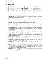
4 - The front panel The front panel 1 23 INPUT LEVEL 0 -∞ +10 LR L R CLIP -6 -12 -18 -24 -30 -36 -42 MEMORY 4 5 7 89 : GRAPHIC EQUALIZER F G NOTCH 1 2 3 Q 4 HPF LPF MEMORY STORE RECALL DISPLAY FLAT UTILITY L R BYPASS POWER ON OFF 6 AB From left to right, the controls on the front panel are: 1 INPUT LEVEL - two concentric rotary controls (inner control is left channel) to adjust the level of the signal fed into the YDG2030. 2 Level meters - L and R. These meters come after the A-D convertors in the signal chain. A "CLIP" indication therefore indicates digital distortion, and the input levels should be adjusted so that the "CLIP" indicator never lights. 3 Memory - this 2-digit LED indicator shows the current memory area. 4 Screen - this 56 x 128 pixel display gives a graphic representation of the current equalization settings. It is also used to display other settings which you can edit using the front panel controls. 5 Rotary encoders - the F, G and Q controls are used primarily for setting the Frequency, Gain and Q of equalization bands. When editing utility settings, they may also be used for editing data. 6 NOTCH, HPF and LPF selectors and indicators - these keys are used to select and deselect the notch filters, HPF and LPF used in an equalization setting. The indicators show which filters are in effect for this equalization setting. 7 MEMORY keys - the [STORE], [RECALL], [^] and [%] keys are used to read and write settings stored in the 40 memory areas. 8 DISPLAY key - pressing this key will change the information displayed on the screen - graphic EQ, notch filter, sweep frequency etc. 9 FLAT key - pressing this key will return the graphic equalizer to a "flat" setting. The notch filters, HPF and LPF will not be affected. 0 UTILITY key - pressing this key will cycle through a range of screens, allowing you to set up various system parameters for the unit. A [L/] keys - you can make equalization settings for the left and right channels independently. These keys allow you to select which channel you are editing. By pressing one of these keys, holding it down, and then pressing the other, you can edit the parameters of both channels simultaneously. B BYPASS key - when pressed, the signal fed into the unit will bypass the internal circuitry, and will be re-output "as is". YDG2030
-
 1
1 -
 2
2 -
 3
3 -
 4
4 -
 5
5 -
 6
6 -
 7
7 -
 8
8 -
 9
9 -
 10
10 -
 11
11 -
 12
12 -
13
-
14
-
15
-
16
-
17
-
18
-
19
-
20
-
21
-
22
-
23
-
24
-
25
-
26
-
27
 |
 |
