Yamaha YDG2030 YDG2030 Owners Manual - Page 7
The rear panel
 |
View all Yamaha YDG2030 manuals
Add to My Manuals
Save this manual to your list of manuals |
Page 7 highlights
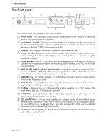
The rear panel 1 2 Y-485 MIDI THRU OUT IN 3 OUTPUT R L -20dB +4dB 5 - The rear panel 4 INPUT R L -20dB +4dB 5 1 Y-485 - these bi-directional connectors are used to connect the unit on a network "chain" using the Y-485 control protocol. They do not carry audio signals. When making a Y-485 connection, either terminal may be used for IN or OUT. Please use digital audio cable (impedance 90 ~ 120 Ω shield type equilibrium transmission cable) for connection with periphery equipment. Using general analog audio cable (impedance 40 ~ 50 Ω shield type equilibrium transmission cable) could cause trouble such as signal reflection due to mismatching impedance and transmission waveform turbulence. Waveform turbulence is especially noticeable with long cables, and with multi cable longer than 10 meters. If the length of the cable is longer than 100 meters, it is recommended that it should be terminated with a resistor matching the impedance of the cable (connect a resistor of approx. 100 Ω between Pin 2 and Pin 3). 2 MIDI IN, OUT and THRU - these terminals are used for MIDI control of the unit. IN is used to receive MIDI data, THRU passes along information received at the IN terminal, and OUT transmits data originated by the unit. 3 OUTPUT (L, R) - these balanced XLR-type connectors output the signal from the unit. 4 INPUT (L, R) - these balanced XLR-type connectors are used to input signals to the unit. 5 Level switches - both the input and output connectors may be set to nominal levels of +4dB or -20dB. When connecting other equipment, refer to the specifications of the other units to match the signal levels correctly. YDG2030
-
 1
1 -
 2
2 -
 3
3 -
 4
4 -
 5
5 -
 6
6 -
 7
7 -
 8
8 -
 9
9 -
 10
10 -
 11
11 -
 12
12 -
13
-
14
-
15
-
16
-
17
-
18
-
19
-
20
-
21
-
22
-
23
-
24
-
25
-
26
-
27
 |
 |
