eMachines D520 eMachines D720/D520 Series Service Guide - Page 107
Replacing the LCD Module
 |
View all eMachines D520 manuals
Add to My Manuals
Save this manual to your list of manuals |
Page 107 highlights
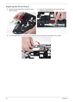
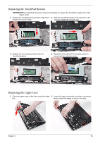
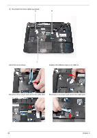
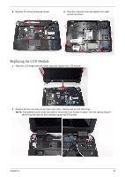
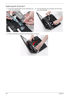
4. Replace the seven screws as shown. 5. Turn the computer over and replace the eight screws as shown. Replacing the LCD Module 1. Align the LCD hinges with the lower case and replace the LCD module. 2. Replace the four securing screws (two each side), starting with the left side hinge. NOTE: Two different screw sizes are used to secure the LCD module in place. The red callouts require M2.5*8 screws and the blue callouts require M2.5*5 screws. Chapter 3 97
-
 1
1 -
2
-
3
-
4
-
5
-
6
-
7
-
8
-
9
-
10
-
11
-
12
-
13
-
14
-
15
-
16
-
17
-
18
-
19
-
20
-
21
-
22
-
23
-
24
-
25
-
26
-
27
-
28
-
29
-
30
-
31
-
32
-
33
-
34
-
35
-
36
-
37
-
38
-
39
-
40
-
41
-
42
-
43
-
44
-
45
-
46
-
47
-
48
-
49
-
50
-
51
-
52
-
53
-
54
-
55
-
56
-
57
-
58
-
59
-
60
-
61
-
62
-
63
-
64
-
65
-
66
-
67
-
68
-
69
-
70
-
71
-
72
-
73
-
74
-
75
-
76
-
77
-
78
-
79
-
80
-
81
-
82
-
83
-
84
-
85
-
86
-
87
-
88
-
89
-
90
-
91
-
92
-
93
-
94
-
95
-
96
-
97
-
98
-
99
-
100
-
101
-
 102
102 -
 103
103 -
 104
104 -
 105
105 -
 106
106 -
 107
107 -
 108
108 -
 109
109 -
 110
110 -
 111
111 -
 112
112 -
113
-
114
-
115
-
116
-
117
-
118
-
119
-
120
-
121
-
122
-
123
-
124
-
125
-
126
-
127
-
128
-
129
-
130
-
131
-
132
-
133
-
134
-
135
-
136
-
137
-
138
-
139
-
140
-
141
-
142
-
143
-
144
-
145
-
146
-
147
-
148
-
149
-
150
-
151
-
152
-
153
-
154
-
155
-
156
-
157
-
158
-
159
-
160
-
161
-
162
-
163
-
164
-
165
-
166
-
167
-
168
-
169
-
170
-
171
-
172
-
173
-
174
 |
 |
Chapter 3
97
Replacing the LCD Module
4.
Replace the seven screws as shown.
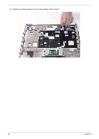
5.
Turn the computer over and replace the eight
screws as shown.
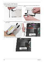
1.
Align the LCD hinges with the lower case and replace the LCD module.
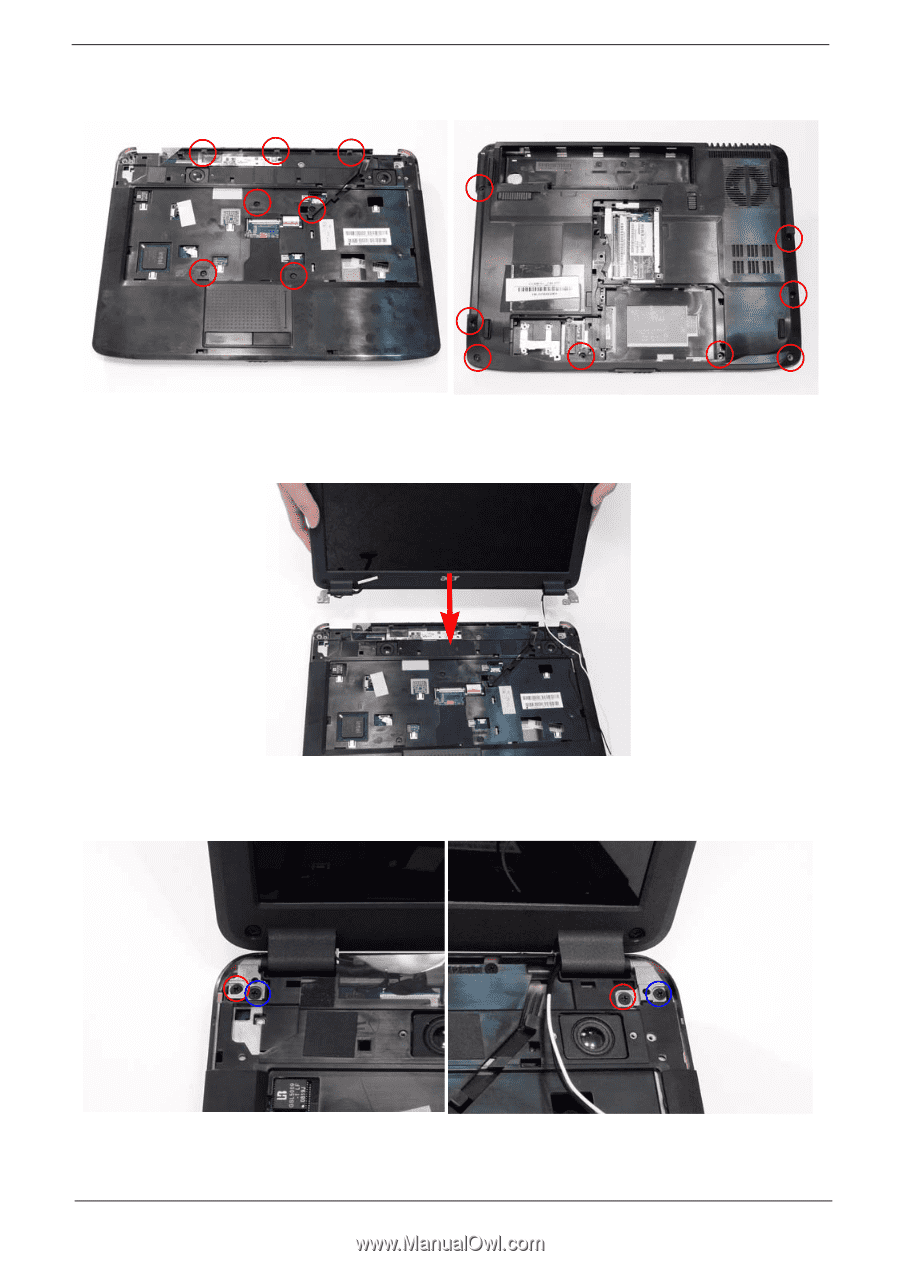
2.
Replace the four securing screws (two each side), starting with the left side hinge.
NOTE:
Two different screw sizes are used to secure the LCD module in place. The red callouts require
M2.5*8 screws and the blue callouts require M2.5*5 screws.