eMachines D520 eMachines D720/D520 Series Service Guide - Page 86
LCD Module Disassembly Process
 |
View all eMachines D520 manuals
Add to My Manuals
Save this manual to your list of manuals |
Page 86 highlights
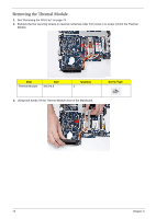
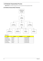
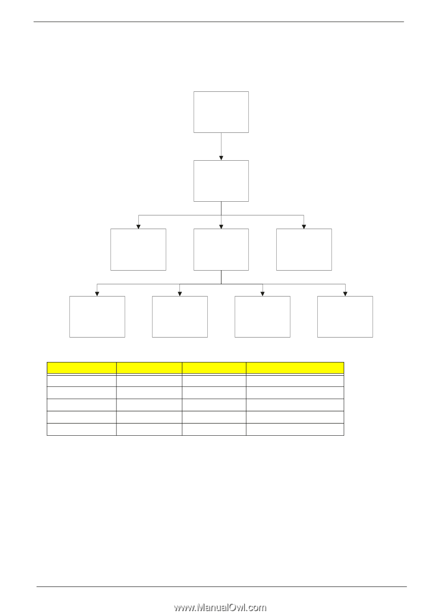
LCD Module Disassembly Process IMPORTANT:The outside housing and color may vary from the mass produced model. LCD Module Disassembly Flowchart Remove LCD Panel from Main Unit before proceeding Rem ove LCD Bezel Rem ove Inverter Board Rem ove LCD Panel Rem ove Camera Module Rem ove LCD FPC Cable Rem ove LCD Brackets Rem ove Antennas Rem ove MIC Cable Screw List Step LCD Bezel Inverter Board Camera Module LCD Panel LCD Brackets Screw M2.5*5 M2.5*5 M2*L3 M2.5*5 M2*L3 Quantity 4 1 1 2 8 Part No. 86.AT902.002 86.AT902.002 86.AT902.003 86.AT902.002 86.AT902.003 76 Chapter 3
-
 1
1 -
2
-
3
-
4
-
5
-
6
-
7
-
8
-
9
-
10
-
11
-
12
-
13
-
14
-
15
-
16
-
17
-
18
-
19
-
20
-
21
-
22
-
23
-
24
-
25
-
26
-
27
-
28
-
29
-
30
-
31
-
32
-
33
-
34
-
35
-
36
-
37
-
38
-
39
-
40
-
41
-
42
-
43
-
44
-
45
-
46
-
47
-
48
-
49
-
50
-
51
-
52
-
53
-
54
-
55
-
56
-
57
-
58
-
59
-
60
-
61
-
62
-
63
-
64
-
65
-
66
-
67
-
68
-
69
-
70
-
71
-
72
-
73
-
74
-
75
-
76
-
77
-
78
-
79
-
80
-
 81
81 -
 82
82 -
 83
83 -
 84
84 -
 85
85 -
 86
86 -
 87
87 -
 88
88 -
 89
89 -
 90
90 -
 91
91 -
92
-
93
-
94
-
95
-
96
-
97
-
98
-
99
-
100
-
101
-
102
-
103
-
104
-
105
-
106
-
107
-
108
-
109
-
110
-
111
-
112
-
113
-
114
-
115
-
116
-
117
-
118
-
119
-
120
-
121
-
122
-
123
-
124
-
125
-
126
-
127
-
128
-
129
-
130
-
131
-
132
-
133
-
134
-
135
-
136
-
137
-
138
-
139
-
140
-
141
-
142
-
143
-
144
-
145
-
146
-
147
-
148
-
149
-
150
-
151
-
152
-
153
-
154
-
155
-
156
-
157
-
158
-
159
-
160
-
161
-
162
-
163
-
164
-
165
-
166
-
167
-
168
-
169
-
170
-
171
-
172
-
173
-
174
 |
 |
76
Chapter 3
LCD Module Disassembly Process
IMPORTANT:
The outside housing and color may vary from the mass produced model.
LCD Module Disassembly Flowchart
Screw List
Step
Screw
Quantity
Part No.
LCD Bezel
M2.5*5
4
86.AT902.002
Inverter Board
M2.5*5
1
86.AT902.002
Camera Module
M2*L3
1
86.AT902.003
LCD Panel
M2.5*5
2
86.AT902.002
LCD Brackets
M2*L3
8
86.AT902.003
Remove
Inverter Board
Remove
LCD Panel
Remove
LCD Bezel
Remove
LCD FPC Cable
Remove
Camera Module
Remove LCD
Panel from Main
Unit before
proceeding
Remove
LCD Brackets
Remove
Antennas
Remove
MIC Cable