2013 Chrysler Town & Country User Guide - Page 105
2013 Chrysler Town & Country Manual

Page 105 highlights
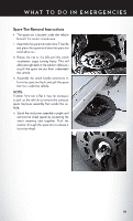
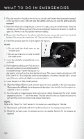
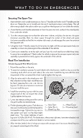
W H AT TO D O I N E M E R G E N C I E S Securing The Spare Tire 1. Assemble the winch handle extensions to form a T-handle and fit the winch T-handle over the drive nut. Rotate the nut to the left until the winch mechanism stops turning freely. This will allow enough slack in the cable to allow you to pull the wheel spacer out from under the vehicle. 2. Assemble the winch handle extensions to form the spare tire hook, and pull the wheel spacer from under the vehicle. 3. Turn the compact spare tire so that the valve stem is down, and place the tire into the spare tire/cover assembly. Slide the wheel spacer through the center of the wheel and spare tire/cover assembly, so that the two retainer tabs snap out and engage the spare tire cover on the opposite side. 4. Using the winch T-handle, rotate the drive nut to the right until the compact spare tire/cover assembly is drawn into place against the underside of the vehicle. 5. Continue to rotate the nut to the right until you hear the winch mechanism click three times. It cannot be overtightened. Check under the vehicle to ensure the compact spare tire/cover assembly is positioned correctly against the underside of the vehicle. Road Tire Installation Vehicles Equipped With Wheel Covers 1. Mount the road tire on the axle. 2. To ease the installation process for steel wheels with wheel covers, install two lug nuts on the mounting studs which are on each side of the valve stem. Install the lug nuts with the cone shaped end of the nut toward the wheel. Lightly tighten the lug nuts. 3. Align the valve notch in the wheel cover with the valve stem on the wheel. Install the cover by hand, snapping the cover over the two lug nuts. Do not use a hammer or excessive force to install the cover. 4. Install the remaining lug nuts with the cone shaped end of the nut toward the wheel. Lightly tighten the lug nuts. 5. Lower the vehicle to the ground by turning the jack handle counterclockwise. 4 - Wheel Cover 6. Finish tightening the lug nuts. Push down on 1 - Valve Stem 5 - Mounting Stud the wrench while at the end of the handle for 2 - Valve Notch 3 - Wheel Lug Nut increased leverage. Tighten the lug nuts in a star pattern until each nut has been tightened twice. The correct tightness of each lug nut is 102 ft/lbs (138 N·m). If in doubt about the correct tightness, have them checked with a torque wrench by your authorized dealer or service station. 7. After 25 miles (40 km) check the lug nut torque with a torque wrench to ensure that all lug nuts are properly seated against the wheel. 103
-
 1
1 -
2
-
3
-
4
-
5
-
6
-
7
-
8
-
9
-
10
-
11
-
12
-
13
-
14
-
15
-
16
-
17
-
18
-
19
-
20
-
21
-
22
-
23
-
24
-
25
-
26
-
27
-
28
-
29
-
30
-
31
-
32
-
33
-
34
-
35
-
36
-
37
-
38
-
39
-
40
-
41
-
42
-
43
-
44
-
45
-
46
-
47
-
48
-
49
-
50
-
51
-
52
-
53
-
54
-
55
-
56
-
57
-
58
-
59
-
60
-
61
-
62
-
63
-
64
-
65
-
66
-
67
-
68
-
69
-
70
-
71
-
72
-
73
-
74
-
75
-
76
-
77
-
78
-
79
-
80
-
81
-
82
-
83
-
84
-
85
-
86
-
87
-
88
-
89
-
90
-
91
-
92
-
93
-
94
-
95
-
96
-
97
-
98
-
99
-
 100
100 -
 101
101 -
 102
102 -
 103
103 -
 104
104 -
 105
105 -
 106
106 -
 107
107 -
 108
108 -
 109
109 -
 110
110 -
111
-
112
-
113
-
114
-
115
-
116
-
117
-
118
-
119
-
120
-
121
-
122
-
123
-
124
-
125
-
126
-
127
-
128
-
129
-
130
-
131
-
132
-
133
-
134
-
135
-
136
-
137
-
138
-
139
-
140
 |
 |
