2007 Infiniti M35 Owner's Manual - Page 151
2007 Infiniti M35 Manual
Page 151 highlights
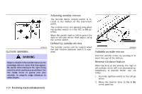
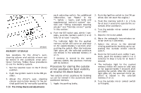
AUTOMATIC DRIVE POSITIONER 3. Choose the right or left outside mirror by operating the outside mirror control switch. 4. The selected outside mirror surface moves downward. 5. When one of the following conditions has occurred, the selected outside mirror surface will return to its original position. The selector lever is moved to any position other than R (Reverse). The outside mirror control switch is set to the center position. The ignition switch is pushed to the LOCK position. For more information regarding this feature and how to save the R (Reverse) mirror tilt-down adjustment in the "Automatic drive positioner" memory, refer to "Automatic drive positioner" later in this section. The automatic drive positioner system has two features: Entry/exit function Memory storage Cancel or activate entry/exit function The entry/exit function can be activated or cancelled by pressing and holding the SET switch for more than 10 seconds while the ignition switch is in the LOCK position. The indicator light will blink once when the function is cancelled, and the indicator light will blink twice when the function is activated. The entry/exit function can also be activated or cancelled from the setting display. See "Vehicle information and settings" in the "4. Monitor, climate, audio, phone and voice recognition systems" section. ENTRY/EXIT FUNCTION This system is designed so that the driver's seat and steering column will automatically move when the automatic transmission selector lever is in the P (Park) position. This allows the driver to get into and out of the driver's seat more easily. The driver's seat will slide backward and the steering wheel will move up when the driver's door is opened with the ignition switch in the LOCK position. The driver's seat and steering wheel will return to the previous positions when one of the following is operated: When the ignition switch is pushed to the ACC position after the driver's door is closed. When the ignition switch is pushed to the ON position. Initialize entry/exit function If the battery cable is disconnected, or if the fuse opens, the entry/exit function will not work though this function was set on before. In such a case, after connecting the battery or replacing with a new fuse, open and close the driver's door more than two times after the ignition switch is pushed to the ON position once, then pushed to the LOCK position. The entry/exit function will be activated. Pre-driving checks and adjustments 3-25
-
 1
1 -
2
-
3
-
4
-
5
-
6
-
7
-
8
-
9
-
10
-
11
-
12
-
13
-
14
-
15
-
16
-
17
-
18
-
19
-
20
-
21
-
22
-
23
-
24
-
25
-
26
-
27
-
28
-
29
-
30
-
31
-
32
-
33
-
34
-
35
-
36
-
37
-
38
-
39
-
40
-
41
-
42
-
43
-
44
-
45
-
46
-
47
-
48
-
49
-
50
-
51
-
52
-
53
-
54
-
55
-
56
-
57
-
58
-
59
-
60
-
61
-
62
-
63
-
64
-
65
-
66
-
67
-
68
-
69
-
70
-
71
-
72
-
73
-
74
-
75
-
76
-
77
-
78
-
79
-
80
-
81
-
82
-
83
-
84
-
85
-
86
-
87
-
88
-
89
-
90
-
91
-
92
-
93
-
94
-
95
-
96
-
97
-
98
-
99
-
100
-
101
-
102
-
103
-
104
-
105
-
106
-
107
-
108
-
109
-
110
-
111
-
112
-
113
-
114
-
115
-
116
-
117
-
118
-
119
-
120
-
121
-
122
-
123
-
124
-
125
-
126
-
127
-
128
-
129
-
130
-
131
-
132
-
133
-
134
-
135
-
136
-
137
-
138
-
139
-
140
-
141
-
142
-
143
-
144
-
145
-
 146
146 -
 147
147 -
 148
148 -
 149
149 -
 150
150 -
 151
151 -
 152
152 -
 153
153 -
 154
154 -
 155
155 -
 156
156 -
157
-
158
-
159
-
160
-
161
-
162
-
163
-
164
-
165
-
166
-
167
-
168
-
169
-
170
-
171
-
172
-
173
-
174
-
175
-
176
-
177
-
178
-
179
-
180
-
181
-
182
-
183
-
184
-
185
-
186
-
187
-
188
-
189
-
190
-
191
-
192
-
193
-
194
-
195
-
196
-
197
-
198
-
199
-
200
-
201
-
202
-
203
-
204
-
205
-
206
-
207
-
208
-
209
-
210
-
211
-
212
-
213
-
214
-
215
-
216
-
217
-
218
-
219
-
220
-
221
-
222
-
223
-
224
-
225
-
226
-
227
-
228
-
229
-
230
-
231
-
232
-
233
-
234
-
235
-
236
-
237
-
238
-
239
-
240
-
241
-
242
-
243
-
244
-
245
-
246
-
247
-
248
-
249
-
250
-
251
-
252
-
253
-
254
-
255
-
256
-
257
-
258
-
259
-
260
-
261
-
262
-
263
-
264
-
265
-
266
-
267
-
268
-
269
-
270
-
271
-
272
-
273
-
274
-
275
-
276
-
277
-
278
-
279
-
280
-
281
-
282
-
283
-
284
-
285
-
286
-
287
-
288
-
289
-
290
-
291
-
292
-
293
-
294
-
295
-
296
-
297
-
298
-
299
-
300
-
301
-
302
-
303
-
304
-
305
-
306
-
307
-
308
-
309
-
310
-
311
-
312
-
313
-
314
-
315
-
316
-
317
-
318
-
319
-
320
-
321
-
322
-
323
-
324
-
325
-
326
-
327
-
328
-
329
-
330
-
331
-
332
-
333
-
334
-
335
-
336
-
337
-
338
-
339
-
340
-
341
-
342
-
343
-
344
-
345
-
346
-
347
-
348
-
349
-
350
-
351
-
352
-
353
-
354
-
355
-
356
-
357
-
358
-
359
-
360
-
361
-
362
-
363
-
364
-
365
-
366
-
367
-
368
-
369
-
370
-
371
-
372
-
373
-
374
-
375
-
376
-
377
-
378
-
379
-
380
-
381
-
382
-
383
-
384
-
385
-
386
-
387
-
388
-
389
-
390
 |
 |