2000 Volvo S40 Owner's Manual - Page 63
2000 Volvo S40 Manual
Page 63 highlights
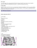
WARNING! The coolant fan may start or continue to operate (for up to 6 minutes) after the engine has been switched off. pg. 110 Fuel/emissions systems Fuel system The fuel system is allelectronic and is microprocessorcontrolled. It can continually compensate for variation in engine load, speed and temperature to give the best economy and power. A mass air flow sensor measures the inducted air. In this way the system can make instantaneous adjustments for changes in air temperature or density, thus always assuring the best economy with the lowest possible exhaust emissions. Heated oxygen sensor This is an emission control system designed to reduce emissions and improve fuel economy. The heated oxygen sensor monitors the composition of the exhaust gases leaving the engine. The exhaust gas analysis is fed into an electronic module. This adjusts the airfuel ratio to provide optimum conditions for combustion and efficient reduction of the three major pollutants (hydrocarbons, carbon monoxide and oxides of nitrogen (NOx) by a threeway catalytic converter. Secondary Air Injection (certain models) This system adds air to the hot exhaust gases as they are expelled from the engine. This causes a secondary combustion of residual hydrocarbons and carbon monoxide, resulting in lower emissions levels in the exhaust gases. Crankcase ventilation The engine is provided with positive crankcase ventilation which prevents crankcase gases from being released into the atmosphere. Instead, the crankcase gases are admitted to the intake manifold and cylinders. Evaporative control system The car is equipped with an evaporative control system which prevents gasoline vapor from being released into the atmosphere. The system consists of a fuel tank with filler pipe and cap, a rollover valve, a Fill Limit Vent Valve (FLVV), vapor vent lines, a charcoal canister, a purge line, a purge control valve and engine connections. In addition, there is a pressure sensor connected to the fuel tank and a filter-protected Canister Close Valve (CCV) on the atmospheric side of the canister, for system diagnosis. The gasoline vapor is channeled through the rollover valve and the FLVV via the vapor vent lines into the charcoal canister, where it is stored. When the engine is started, the gasoline vapor is drawn from the charcoal canister to the engine's air intake system and into the combustion process. NOTE: · If the fuel filler cap is not closed tightly or if the engine is running when the car is refueled, the Malfunction Indicator Lamp may indicate a fault.
-
 1
1 -
2
-
3
-
4
-
5
-
6
-
7
-
8
-
9
-
10
-
11
-
12
-
13
-
14
-
15
-
16
-
17
-
18
-
19
-
20
-
21
-
22
-
23
-
24
-
25
-
26
-
27
-
28
-
29
-
30
-
31
-
32
-
33
-
34
-
35
-
36
-
37
-
38
-
39
-
40
-
41
-
42
-
43
-
44
-
45
-
46
-
47
-
48
-
49
-
50
-
51
-
52
-
53
-
54
-
55
-
56
-
57
-
 58
58 -
 59
59 -
 60
60 -
 61
61 -
 62
62 -
 63
63 -
 64
64 -
 65
65 -
 66
66 -
 67
67 -
 68
68 -
69
-
70
-
71
-
72
-
73
-
74
-
75
-
76
-
77
-
78
-
79
-
80
-
81
-
82
-
83
-
84
 |
 |