2012 Yamaha Motorsports Raider SCL Owners Manual - Page 71
2012 Yamaha Motorsports Raider SCL Manual

Page 71 highlights
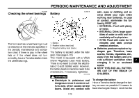
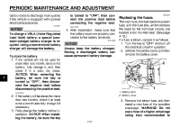
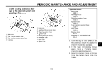
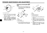
PERIODIC MAINTENANCE AND ADJUSTMENT avoid causing extensive damage to the electrical system and possibly a fire. [EWA15131] Specified fuses: Main fuse: 50.0 A Headlight fuse: 20.0 A Signaling system fuse: 15.0 A Ignition fuse: 20.0 A Fuel injection system fuse: 15.0 A ECU fuse: 15.0 A Backup fuse: 3.0 A Auxiliary DC connector fuse: 3.0 A 8 2 3 7 1. 2. 3. 4. 5. 6. 7. 8. Fuse box Auxiliary DC connector fuse Signaling system fuse Ignition fuse Backup fuse (for clock) Headlight fuse ECU fuse Spare fuse 1. 2. 3. 4. Main fuse Fuel injection system fuse Fuel injection system spare fuse Fuse box 4. Turn the key to "ON" and turn on the electrical circuit in question to check if the device operates. 5. If the fuse immediately blows again, have a Yamaha dealer check the electrical system. 6. Install the battery cover, and then hook the battery band onto the holder. 7 7-28
-
 1
1 -
2
-
3
-
4
-
5
-
6
-
7
-
8
-
9
-
10
-
11
-
12
-
13
-
14
-
15
-
16
-
17
-
18
-
19
-
20
-
21
-
22
-
23
-
24
-
25
-
26
-
27
-
28
-
29
-
30
-
31
-
32
-
33
-
34
-
35
-
36
-
37
-
38
-
39
-
40
-
41
-
42
-
43
-
44
-
45
-
46
-
47
-
48
-
49
-
50
-
51
-
52
-
53
-
54
-
55
-
56
-
57
-
58
-
59
-
60
-
61
-
62
-
63
-
64
-
65
-
 66
66 -
 67
67 -
 68
68 -
 69
69 -
 70
70 -
 71
71 -
 72
72 -
 73
73 -
 74
74 -
 75
75 -
 76
76 -
77
-
78
-
79
-
80
-
81
-
82
-
83
-
84
-
85
-
86
-
87
-
88
-
89
-
90
-
91
-
92
-
93
-
94
-
95
-
96
-
97
-
98
-
99
-
100
 |
 |
