3M M2256PW User Manual
3M M2256PW Manual
 |
View all 3M M2256PW manuals
Add to My Manuals
Save this manual to your list of manuals |
3M M2256PW manual content summary:
- 3M M2256PW | User Manual - Page 1
3M™ Display M2256PW User Guide Read and understand all safety information contained in this document before using this product. 3M Touch Systems, Inc. Proprietary Information - 3M M2256PW | User Manual - Page 2
. Copyright © 2010 3M All rights reserved. Document Title: 3M Display M2256PW User Guide Document Number: 37531, Version 02 3M, the 3M logo, MicroTouch, and the MicroTouch logo are either registered trademarks or trademarks of 3M in the United States and/or other countries. Windows and/or other - 3M M2256PW | User Manual - Page 3
14 Access to the Video Controls 14 Adjusting the M2256PW Video Display 15 Enabling Your M2256PW Display Windows™ 7 USB Compatibility 18 All Other Platforms 18 Multitouch Application Support 18 Installing 3M™ MicroTouch™ Software 19 Video Alignment ...19 3M Touch Systems, Inc. Proprietary - 3M M2256PW | User Manual - Page 4
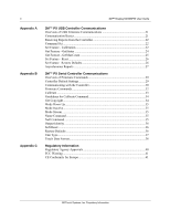
4 Appendix A Appendix B Appendix C 3M™ Display M2256PW User Guide 3M™ PX USB Controller Communications Overview of USB Firmware Communications 21 Communication Basics 21 Receiving Reports from the Controller 22 Command Set ...22 Set Feature - Calibration 22 Get Feature - GetStatus 24 Get - 3M M2256PW | User Manual - Page 5
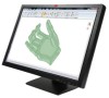
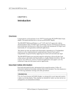
of your 3M™ Touch Systems M2256PW Multi-Touch display. This guide describes how to set up your M2256PW Display. The M2256PW Multi-touch Display is a 22" LCD with 16:10 aspect ratio with an attached desktop stand. 3M Multi-touch Technology, based on 3M Projected Capacitive touch technology and - 3M M2256PW | User Manual - Page 6
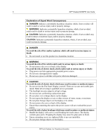
6 3M™ Display M2256PW User Guide Explanation of Signal Word touch sensor. The display contains glass parts. Dropping the display may cause the glass parts to break. • Ensure mounting screws are tightened fully to prevent instability. • Do not place foreign objects on the display. 3M Touch Systems - 3M M2256PW | User Manual - Page 7
your display and touch sensor clean. • Adjust the display video controls. • Do not install the display in a place where ventilation may be hindered. Always maintain adequate ventilation to protect the display from overheating and to promote reliable and continued operation. 3M Touch Systems, Inc - 3M M2256PW | User Manual - Page 8
inside the display or stain the bezel. 3M Touch Systems Support Services 3M Touch Systems, Inc. provides extensive support services through our website and technical support organization. Visit the 3M Touch Systems website at http://www.3m.com/touch/, where you can download MT 7 software and drivers - 3M M2256PW | User Manual - Page 9
3M™ Display M2256PW User Guide 9 You can contact 3M Touch Systems, Inc. Technical Support (US only -- Eastern Standard Time) by calling the hot line, sending email or a fax. • Technical Support Hot Line: 978-659-9200 • Technical Support Fax: 978-659-9400 • Toll Free: 1-866-407-6666 (Option 3) • - 3M M2256PW | User Manual - Page 10
10 3M™ Display M2256PW User Guide CHAPTER 2 Setting up Your M2256PW Display This chapter describes how to set up your 3M Touch Systems M2256PW Display. You need to complete the following tasks: • Unpack the components • Connect the video, touch display cables, and power cables • Power on the - 3M M2256PW | User Manual - Page 11
3M™ Display M2256PW User Guide 11 Unpacking Your Touch Display Carefully unpack the carton and inspect the contents. Your M2256PW Display includes the following cables and accessories: • USB and RS-232 serial communication cables • DVI and VGA video cables • Audio cable • US and European power - 3M M2256PW | User Manual - Page 12
M4 x 8 mm screws to secure the VESA mount stand. Follow the manufacturer's instructions included with the mounting device to properly attach your display. Note: Do not use longer screws as they could potentially damage electronics inside the display. 3M Touch Systems, Inc. Proprietary Information - 3M M2256PW | User Manual - Page 13
3M™ Display M2256PW User Guide 13 Video Card Requirements Before you connect your touch display, make sure your computer has a video card installed that supports the native video resolution of 1680 x 1050 for the M2256PW display. If you need information on installing a video card or video driver, - 3M M2256PW | User Manual - Page 14
screen menu and adjust the phase, image position, contrast, and brightness. Before you make any adjustments: • Be sure to adjust the controls in your normal lighting conditions. • Display a test image or pattern whenever you adjust the video. Menu/Select Down Up Auto/Exit Power LED 3M Touch Systems - 3M M2256PW | User Manual - Page 15
3M™ Display M2256PW User Guide 15 Adjusting the M2256PW Video Display Your M2256PW Display has four controls to adjust the video display. • Menu - Shows or hides the on screen display menu. • Select -- Highlights the current menu option or saves the current setting. Press ▲ or ▼ to change the - 3M M2256PW | User Manual - Page 16
3M™ Display M2256PW User Guide vertical bars of video noise on your screen either left or right. V POSITION (Vertical position) Moves images vertically on screen either up or down LANGUAGE Sets the language for the OSD -- the choices are English, French, German, Italian, and Chinese 3M Touch Systems - 3M M2256PW | User Manual - Page 17
3M™ Display M2256PW User Guide OSD Choices 17 Description TOOLS Choices are OSD Timing, OSD Horizontal, OSD Vertical OSD TIMING Adjust how long the menu remains on the screen. Submenu choices are: Recall, Sharpness, or Exit OSD HORIZONTAL and VERTICAL Adjusts the position of the OSD on your screen - 3M M2256PW | User Manual - Page 18
3M™ Display M2256PW User Guide CHAPTER 3 Enabling Your M2256PW Display Windows™ 7 USB Compatibility 3M multi-touch technology works seamlessly with the Windows™ 7 operating system. The Multi-touch display supports USB HID for direct communication. The M2256PW display leverages all the multi-touch - 3M M2256PW | User Manual - Page 19
3M™ Display M2256PW User Guide 19 Installing 3M™ MicroTouch™ Software Remember that Windows™ 7 does not require any additional software to enable multitouch functionality. However, for Windows™ XP, Vista or Linux® operating systems, 3M™ MicroTouch™ Software enables your M2256PW display to work - 3M M2256PW | User Manual - Page 20
20 3M™ Display M2256PW User Guide If you are using 3M™ MicroTouch™ MT 7 Software, launch the MT 7 Control Panel and follow the instructions on the Main tab. You'll be asked to touch 3 targets. If you are writing your own drivers, you should provide your own video alignment tool. Use the Paint - 3M M2256PW | User Manual - Page 21
3M™ Display M2256PW User Guide 21 APPENDIX A 3M™ PX USB Controller Communications This appendix is intended for software developers only and discusses the fundamentals of communicating with the PX controller. The firmware commands, which are usually issued by a driver drivers, 3M Touch Systems - 3M M2256PW | User Manual - Page 22
22 3M™ Display M2256PW User Guide You need to know product ID (0502H) and the vendor ID (0596H) to write your own driver. These values are required do a Calibrate Extended style calibration. The controller will autoorient on this 2 point calibration. 3M Touch Systems, Inc. Proprietary Information - 3M M2256PW | User Manual - Page 23
3M™ Display M2256PW User Guide 23 Table Windows-based display is 1680 x 1050. The Calibrate Extended command calculates the amount to move inward as follows: • Amount to move inward in the X direction: 1680 x 1/8 = 210 • Amount to move inward in the Y direction: 1050 x 1/8 = 131 3M Touch Systems - 3M M2256PW | User Manual - Page 24
24 3M™ Display M2256PW User Guide The Calibrate Extended command Windows-based system. Your operating system may be different. The illustration below shows the coordinates of the calibration targets and display corners. The corners show the video coordinates in parentheses and the touch screen - 3M M2256PW | User Manual - Page 25
3M™ Display M2256PW User Guide 25 POC Status - The status of the Power-on Checks. Various controller systems are checked at power-up. If any failures in these systems area checksum error Touch screen not connected or potential problem Parameter blocks checksum error Problem with ADCs Cmd Status - 3M M2256PW | User Manual - Page 26
3M™ Display M2256PW User Guide Table 10. Data Stage (controller response) Offset Field 0 Report ID 1 Max Count Size 1 1 Value 0x12 0x1E Description Feature Report ID Number of actual 30 fingers supported a request to restore parameter defaults. 3M Touch Systems, Inc. Proprietary Information - 3M M2256PW | User Manual - Page 27
Touch Report Touch Report Touch Report Size 1 10 10 10 10 10 Value 0x13 See table 16 See table 16 See table 16 See table 16 See table 16 Description Report ID Touch Report Structure Touch Report Structure Touch Report Structure Touch Report Structure Touch Report Structure 3M Touch Systems - 3M M2256PW | User Manual - Page 28
28 3M™ Display M2256PW User Guide Offset 51 61 62 63 Field Touch Report Actual Count Not used Not used Table 16. Touch Report Structure Offset 0 Field Status Size 10 1 1 1 Value See table 16 1 to 60 0 0 Size Value 6 0xXX 1 Touch ID 1 0-255 2 X lsb 1 0xXX 3 X msb 1 0xXX 4 Y - 3M M2256PW | User Manual - Page 29
3M™ Display M2256PW User Guide 29 APPENDIX B 3M™ PX Serial Controller Communications This appendix is intended for software developers only and discusses the fundamentals of communicating with the 3M™ PX serial controller. The firmware commands, which are usually issued by a driver or utility - 3M M2256PW | User Manual - Page 30
30 3M™ Display M2256PW User Guide Data Format Data format refers to the type of packet the controller uses to send the X/Y touch coordinates to the host system. Format Tablet Multitouch is the default format for the 3M™ PX serial controller. In Format Tablet Multitouch, the controller sends 6 - 3M M2256PW | User Manual - Page 31
3M™ Display M2256PW User Guide 31 The header is the first character in the command string : • The command was not formatted correctly. • The system parameters were not set up to allow command execution. • The controller does not support the command. 3M Touch Systems, Inc. Proprietary Information - 3M M2256PW | User Manual - Page 32
32 3M™ Display M2256PW User Guide The terminator is the last character of each response string and any firmware commands. To optimize the performance of the touch controller and simplify the development of custom drivers, 3M Touch Systems recommends you use the commands listed in Table 17 for - 3M M2256PW | User Manual - Page 33
3M™ Display M2256PW User Guide 33 Calibrate Syntax: CX Response: 1 Valid point response. A Valid Point Response ('1') signifies that a touch coordinate was detected and is in range of the expected screen target area. Two valid point responses indicate successful calibration. - 3M M2256PW | User Manual - Page 34
for a Windows-based system. Your operating system may be different. The illustration below shows the coordinates of the calibration targets and display corners. The corners show the video coordinates in parentheses and the touch screen coordinates in brackets. Note that the touch screen coordinates - 3M M2256PW | User Manual - Page 35
3M™ Display M2256PW User Guide 35 Response: Copyright © 2010 3M. All rights reserved. Description: This command is used to get copyright information. Mode Down Up Syntax: MDU Response: 0 Positive response. Description: Limits touch reports to touchdown and liftoff - 3M M2256PW | User Manual - Page 36
36 3M™ Display M2256PW User Guide Output Identity Syntax: OI Response: ADXxxx where: AD = Two ASCII characters that describe the type of 3M Touch Systems controller. Xxxx = This is a unique identifier not necessarily the actual firmware revision number. Description: Returns - 3M M2256PW | User Manual - Page 37
3M™ Display M2256PW User Guide 37 Data Format Operating Mode Return to Factory Calibration Format Tablet Multitouch Mode Stream Yes Note: After you issue a Restore Defaults command, you must recalibrate your sensor. Unit Type UT Responds with an 8-character identity - 3M M2256PW | User Manual - Page 38
38 3M™ Display M2256PW User Guide where: Tt = Two ASCII characters that identify the controller type. AD Indicates the PX series of controllers Ffff = Four ASCII characters that indicate the features supported by the controller. **** Indicates no additional features configured Ss = Two ASCII - 3M M2256PW | User Manual - Page 39
3M™ Display M2256PW User Guide 39 Table 20 Touch Data Format Settings Data Sequence Bits Status - Byte 1 X - Byte 2 X - Byte 3 Y - Byte 4 Y - Byte 5 ID - Byte 6 7 6 5 4 3 2 1 0 1 P1 0 0 0 0 0 0 0 X6 X5 X4 X3 X2 X1 X0 0 X13 X12 X11 - 3M M2256PW | User Manual - Page 40
40 3M™ Display M2256PW User Guide APPENDIX C Regulatory Information Regulatory if not installed and used in accordance with the instructions, may cause harmful interference to radio communications. However, technician for additional suggestions. 3M Touch Systems, Inc. Proprietary Information - 3M M2256PW | User Manual - Page 41
3M™ Display M2256PW User Guide du Règlement sur le matériel brouilleur du Canada. This device complies with Part 15 of use grounded power supply cord and the provided shielded video interface cable with bonded ferrite cores. If a BNC to operate this device. 3M Touch Systems is not responsible for any
-
 1
1 -
 2
2 -
 3
3 -
 4
4 -
 5
5 -
 6
6 -
 7
7 -
8
-
9
-
10
-
11
-
12
-
13
-
14
-
15
-
16
-
17
-
18
-
19
-
20
-
21
-
22
-
23
-
24
-
25
-
26
-
27
-
28
-
29
-
30
-
31
-
32
-
33
-
34
-
35
-
36
-
37
-
38
-
39
-
40
-
41
 |
 |

3M Touch Systems, Inc. Proprietary Information
3M
™
Display M2256PW
User Guide
Read and understand all safety information
contained in this document before using this product.