AIWA CDC-X144 Service Manual - Page 4
AIWA CDC-X144 Manual
 |
View all AIWA CDC-X144 manuals
Add to My Manuals
Save this manual to your list of manuals |
Page 4 highlights
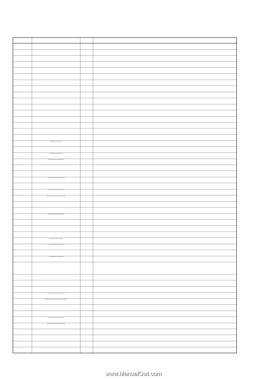
CDC-R104/X104/X144 • IC501 MN101E01KAB (SYSTEM CONTROL) (MAIN BOARD (1/2)) Pin No. Pin Name I/O Pin Description 1 DAVDD - Power supply pin for D/A output converter (+3.3 V) 2 BBE-MP O Not used in this set. (Open) 3 DAVSS - Ground pin for D/A output converter 4 to 6 NCO O Not used in this set. (Open) 7 UNISO O SONY-BUS data signal output Not used in this set. (Open) 8 UNISI I SONY-BUS data signal input Not used in this set. 9 UNICKO O SONY-BUS clock signal output Not used in this set. 10 VDD1 - Power supply pin for internal core (+3.3 V) 11 MMOD I Flash microcomputer write detection signal input Not used in this set. 12 OSCOUT O High speed operation clock signal output (27 MHz) 13 OSCIN I High speed operation clock signal input (27 MHz) 14 VSS1 - Ground pin for internal core 15 XIN I Low speed operation clock signal input (32.768 kHz) 16 XOUT O Low speed operation clock signal output (32.768 kHz) 17 VDD2 - Power supply pin for internal core (+3.3 V) 18 MOD1 - Pull up: "H" 19 RESET I Reset signal input 20 NCO O Not used in this set. (Open) 21 ACC IN I Accessory power supply detection signal input 22 TEST IN I Test mode detection signal input 23 TEL ATT I Telephone attenuate detection signal input 24 ATT O Audio mute control signal output 25 XKEYON O Key power supply control signal output Not used in this set. (Open) 26 NCO O Not used in this set. (Open) 27 KEYACK I Key acknowledge detection signal input 28 TU ATTIN I Tuner mute ZERO cross detection signal input 29, 30 NCO O Not used in this set. (Open) 31 BUIN I Back up power supply detection signal input 32 CD INTQ I CD servo IC CD text pack synchronization signal input 33 CD SO O CD servo IC serial data signal output (for command/text) 34 CD SI I CD servo IC serial data signal input (for command/text) 35 CD SCK O CD servo IC serial clock signal output (for command/text) 36 BUSON O BUS on signal output 37 SYSRST O System reset signal output 38 CD RFOK I CD servo IC RFOK signal input 39 CD RST O CD servo IC reset signal output CD servo IC command/parameter identification signal output 40 CD A0 O Command transmission: "L", Parameter transmission: "H" 41 CD STB O CD servo IC data strob signal output 42 CD MUTE R I Mechadeck mute zero cross detection signal input R 43 CD MUTE L I Mechadeck mute zero cross detection signal input L 44 CD INSW I CD mecha disc in switch detection signal input 45 CD SELFSW I CD mecha self load position detection switch signal input 46 CD LM LO O CD mecha loading motor control signal output 47 CD LM EJ O CD mecha eject motor control signal output 48 CD DSW I CD mecha down switch detection signal input 49 CD LIMIT I CD mecha in-limit switch signal input 50 NCO O Not used in this set. (Open) 51 AREASEL1 I Destination function setting input 1 52 AREASEL2 I Destination function setting input 2 53 AREASEL3 I Destination function setting input 3 16
-
 1
1 -
 2
2 -
 3
3 -
 4
4 -
 5
5 -
 6
6 -
 7
7 -
 8
8 -
 9
9 -
 10
10 -
11
-
12
-
13
-
14
-
15
-
16
-
17
-
18
-
19
-
20
-
21
-
22
-
23
-
24
 |
 |