AIWA CDC-X144 Service Manual - Page 5
AIWA CDC-X144 Manual
 |
View all AIWA CDC-X144 manuals
Add to My Manuals
Save this manual to your list of manuals |
Page 5 highlights
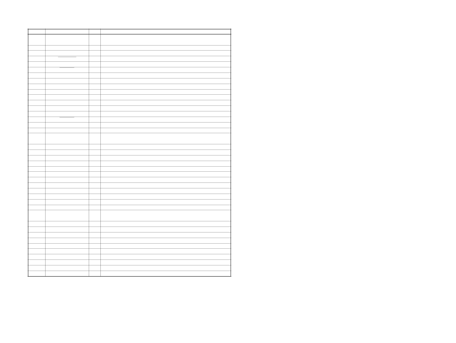
Pin No. 54 55, 56 57 58 59 60 61, 62 63 64 65 66 67 68 69 70 71 to 73 74 75 76 77 78 79 80 81 82 83 84 85 86 to 88 89 90 91 92 93 94 95 96 97 98 99 100 Pin Name LCD CTL NCO DSSA PANEL SW DIAG VOLATT NCO VSS2 TU ATT NCO NS MASK EEP CKO EEP SIO NCO AMPSTB NCO NCO COL SEL LCDSO LCDCE LCDCKO I2C SIO NCO I2C CKO DAVN SIRCS NCO BEEP NCO VDD3 COL SW VSS3 QUALITY VSM KEYIN1 KEYIN0 NCO KEYIN2 RE L METER VREF+ I/O Pin Description "H" output: LCD unit and key confusion, power off O "L" output: LCD unit and key confusion, power on O Not used in this set. (Open) O DSSA on/off change signal output (Cut off rear) I Front panel attachment detection signal input "L": with panel, "H": without panel I Condition signal input from the power IC O Electronic volume attenuate control signal output O Not used in this set. (Open) - Ground pin for I/O port O Tuner mute control signal output O Not used in this set. (Open) O Noise mask signal output O Serial clock signal output for EEPROM communication I/O Serial data signal input/output for EEPROM communication O Not used in this set. (Open) O Power regulator IC standby signal output O Not used in this set. (Open) O Not used in this set. (Open) "H": Front panel illumination green (Initial value) I "L": Front panel illumination amber (Initial value) O Serial data signal output to the LCD driver O Chip enable signal output to the LCD driver O Serial clock signal output to the LCD driver I/O I2C BUS serial data signal input/output O Not used in this set. (Open) O I2C BUS serial clock signal output I RDS data block synchronization detection signal input I Remote control signal input O Not used in this set. (Open) O Beep signal output to the power amp O Not used in this set. (Open) - Power supply pin for I/O port (+3.3 V) "L" input: two color change/initial slave color: amber I "H" input: one color/slave color: white - Ground pin for I/O port I Noise detection signal input I S meter voltage detection signal input I Key signal input 1 I Key signal input 0 O Not used in this set. I Key signal input (EJECT, OFF, SOURCE switch) I Rotary encoder signal input I Level meter voltage detection signal input - Power supply pin for A/D input converter 17 17 CDC-R104/X104/X144
-
 1
1 -
 2
2 -
 3
3 -
 4
4 -
 5
5 -
 6
6 -
 7
7 -
 8
8 -
 9
9 -
 10
10 -
 11
11 -
12
-
13
-
14
-
15
-
16
-
17
-
18
-
19
-
20
-
21
-
22
-
23
-
24
 |
 |