ASRock 775Dual-915GV User Manual - Page 21
Surround Display Feature, 8 Jumpers Setup
 |
View all ASRock 775Dual-915GV manuals
Add to My Manuals
Save this manual to your list of manuals |
Page 21 highlights
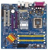
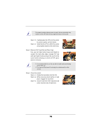
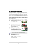
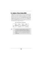
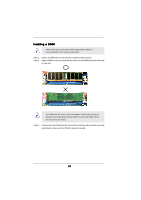
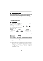
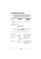
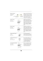
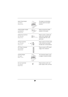
2.7 Surround Display Feature Thanks to ASRock patented AGI8X and AGI Express Technology, this motherboard supports Surround Display upgrade. With the internal onboard VGA and the external add-on AGP VGA card and PCI Express VGA card, you can easily enjoy the benefits of Surround Display feature. Please make sure to set the BIOS onboard VGA selection into "Enabled", and start your computer with onboard VGA if you want this motherboard to support multi-monitors. For the detailed instruction, please refer to the document at the following path in the Support CD: ..\ Surround Display Information 2.8 Jumpers Setup The illustration shows how jumpers are setup. When the jumper cap is placed on pins, the jumper is "Short". If no jumper cap is placed on pins, the jumper is "Open". The illustration shows a 3-pin jumper whose pin1 and pin2 are "Short" when jumper cap is placed on these 2 pins. Jumper Setting Description PS2_USB_PWR1 1_2 (see p.12 No. 1) 2_3 Short pin2, pin3 to enable +5VSB (standby) for PS/2 +5V +5VSB or USB wake up events. Note: To select +5VSB, it requires 2 Amp and higher standby current provided by power supply. JR1(see p.12 No. 25) JL1(see p.12 No. 25) JR1 JL1 Note: If the jumpers JL1 and JR1 are short, both the front panel and the rear panel audio connectors can work. Clear CMOS (CLRCMOS1, 2-pin jumper) (see p.12 No. 28) 2-pin jumper Note: CLRCMOS1 allows you to clear the data in CMOS. The data in CMOS includes system setup information such as system password, date, time, and system setup parameters. To clear and reset the system parameters to default setup, please turn off the computer and unplug the power cord from the power supply. After waiting for 15 seconds, use a jumper cap to short 2 pins on CLRCMOS1 for 5 seconds. 21
-
 1
1 -
2
-
3
-
4
-
5
-
6
-
7
-
8
-
9
-
10
-
11
-
12
-
13
-
14
-
15
-
 16
16 -
 17
17 -
 18
18 -
 19
19 -
 20
20 -
 21
21 -
 22
22 -
 23
23 -
 24
24 -
 25
25 -
 26
26 -
27
-
28
-
29
-
30
-
31
-
32
-
33
-
34
-
35
-
36
-
37
-
38
-
39
-
40
-
41
-
42
 |
 |