ASRock 880GMH/U3S3 User Manual - Page 28
Front Panel Audio Header - no sound
 |
View all ASRock 880GMH/U3S3 manuals
Add to My Manuals
Save this manual to your list of manuals |
Page 28 highlights
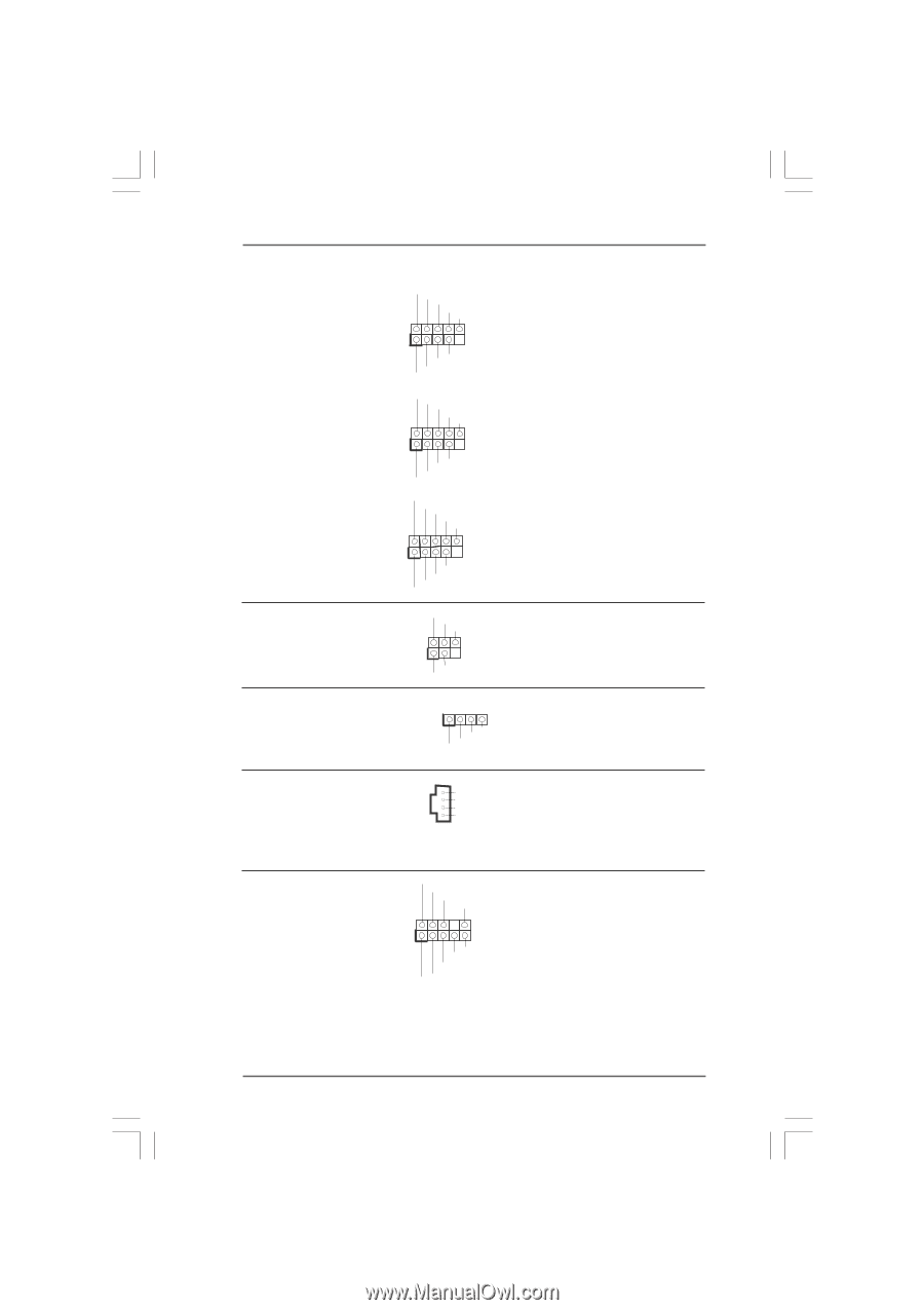
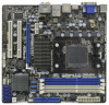
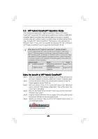
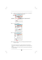
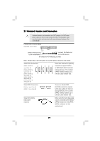
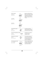
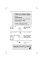
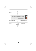
USB 2.0 Headers (9-pin USB10_11) (see p.12 No. 22) (9-pin USB8_9) (see p.12 No. 12) (9-pin USB6_7) (see p.12 No. 11) USB_PWR P-11 P+11 GND DUMMY 1 GND P+10 P-10 USB_PWR USB_PWR P-9 P+9 GND DUMMY 1 GND P+8 P-8 USB_PWR USB_PWR P-7 P+7 GND DUMMY 1 GND P+6 P-6 USB_PWR Infrared Module Header (5-pin IR1) (see p.12 No. 26) IRTX +5V DUMMY 1 GND IRRX Consumer Infrared Module Header (4-pin CIR1) (see p.12 No. 9) 1 GND IRTX IRRX ATX+5VSB Internal Audio Connectors (4-pin CD1) (CD1: see p.12 No. 33) CD-L GND GND CD-R CD1 Front Panel Audio Header (9-pin HD_AUDIO1) (see p.12, No. 32) GND PRESENCE# MIC_RET OUT_RET 1 OUT2_L J_SENSE OUT2_R MIC2_R MIC2_L Besides four default USB 2.0 ports on the I/O panel, there are three USB 2.0 headers on this motherboard. Each USB 2.0 header can support two USB 2.0 ports. This header supports an optional wireless transmitting and receiving infrared module. This header can be used to connect the remote controller receiver. This connector allows you to receive stereo audio input from sound sources such as a CD-ROM, DVD-ROM, TV tuner card, or MPEG card. This is an interface for the front panel audio cable that allows convenient connection and control of audio devices. 28
-
 1
1 -
2
-
3
-
4
-
5
-
6
-
7
-
8
-
9
-
10
-
11
-
12
-
13
-
14
-
15
-
16
-
17
-
18
-
19
-
20
-
21
-
22
-
 23
23 -
 24
24 -
 25
25 -
 26
26 -
 27
27 -
 28
28 -
 29
29 -
 30
30 -
 31
31 -
 32
32 -
 33
33 -
34
-
35
-
36
-
37
-
38
-
39
-
40
-
41
-
42
-
43
-
44
-
45
-
46
-
47
-
48
-
49
-
50
-
51
-
52
-
53
-
54
-
55
-
56
-
57
-
58
 |
 |