ASRock 939A8X-M User Manual - Page 18
ATX 12V Connector
 |
View all ASRock 939A8X-M manuals
Add to My Manuals
Save this manual to your list of manuals |
Page 18 highlights
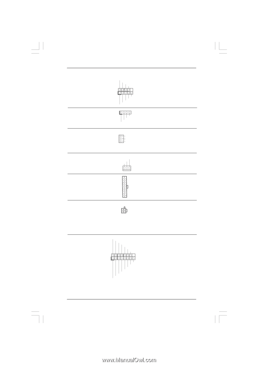
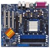
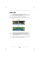
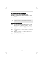
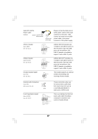
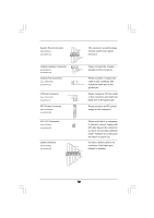
System Panel Connector (9-pin PANEL1) (see p.8 item 12) Chassis Speaker Connector pin SPEAKER 1) (see p.8 item 13) PLED+ PLEDPWRBTN# GND 1 DUMMY RESET# GND HDLEDHDLED+ 1 SPEAKER DUMMY DUMMY +5V This connector accommodates several system front panel functions. Please connect the chassis ( 4 speaker to this connector. Chassis Fan Connector (3-pin CHA_FAN1) (see p.8 item 11) GND +12V CHA_FAN_SPEED Please connect a chassis fan cable to this connector and match the black wire to the ground pin. CPU Fan Connector (3-pin CPU_FAN1) (see p.8 item 5) CPU_FAN_SPEED +12V GND Please connect a CPU fan cable to this connector and match the black wire to the ground pin. ATX Power Connector (20-pin ATXPWR1) (see p.8 item 25) Please connect an ATX power supply to this connector. ATX 12V Connector (4-pin ATX12V1) (see p.8 item 28) Game Connector (15-pin GAME1) (see p.8 item 19) +5V JBB1 JBX MIDI_OUT JBY JBB2 MIDI_IN 1 +5V JAB2 JAY GND GND JAX JAB1 +5V Please note that it is necessary to connect a power supply with ATX 12V plug to this connector so that it can provides sufficient power. Failing to do so will cause the failure to power up. Connect a Game cable to this connector if the Game port bracket is installed. 18
-
 1
1 -
2
-
3
-
4
-
5
-
6
-
7
-
8
-
9
-
10
-
11
-
12
-
 13
13 -
 14
14 -
 15
15 -
 16
16 -
 17
17 -
 18
18 -
 19
19 -
 20
20 -
 21
21 -
 22
22 -
 23
23 -
24
-
25
-
26
-
27
-
28
-
29
-
30
-
31
-
32
-
33
-
34
-
35
-
36
-
37
 |
 |