ASRock 939A8X-M User Manual - Page 8
Motherboard Layout
 |
View all ASRock 939A8X-M manuals
Add to My Manuals
Save this manual to your list of manuals |
Page 8 highlights
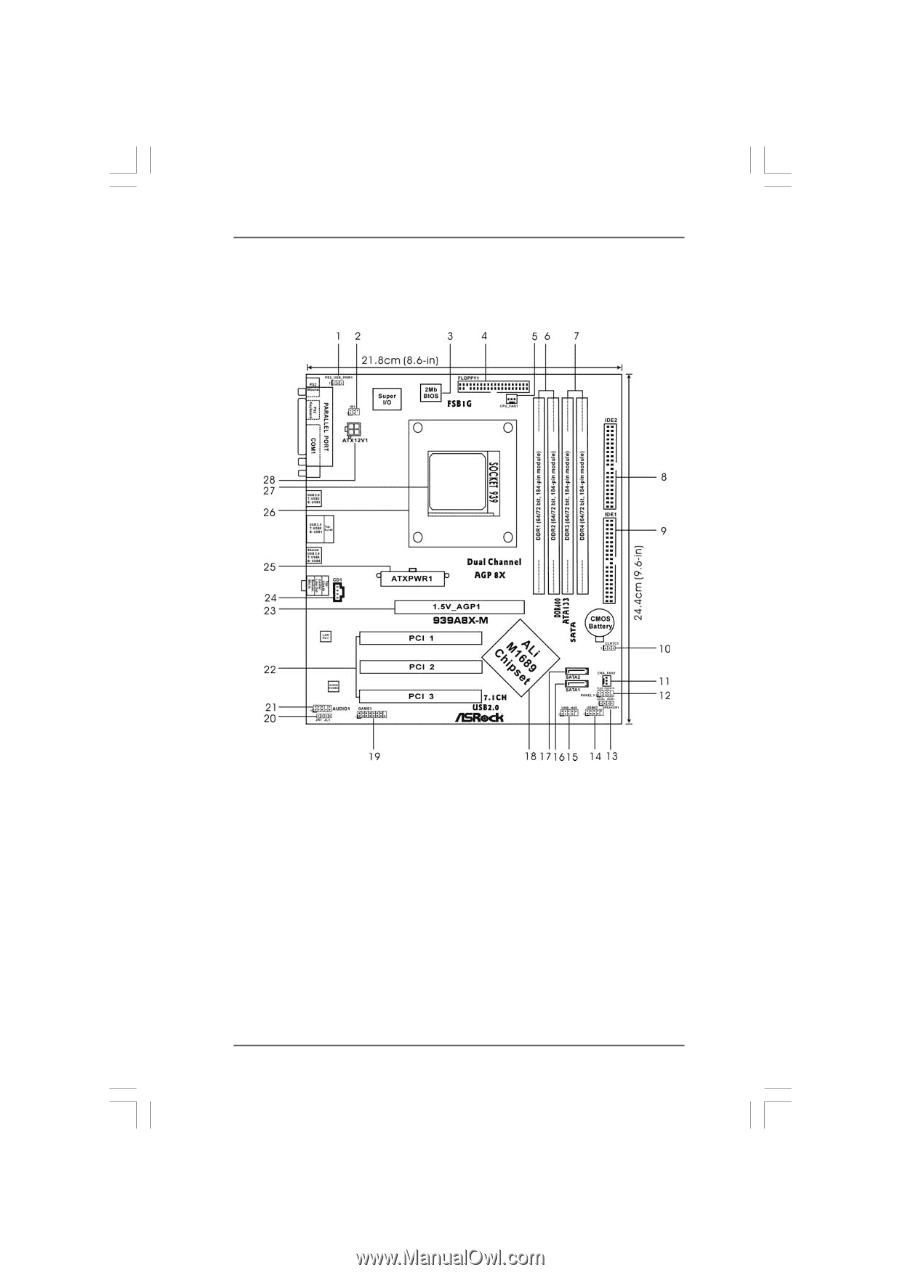
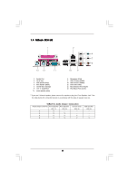
1.3 Motherboard Layout 1 PS2_USB_PWR1 Jumper 2 Infrared Module Header (IR1) 3 Flash Memory 4 Floppy Connector (FLOPPY1) 5 CPU Fan Connector (CPU_FAN1) 6 2 x 184-pin DDR DIMM Slots (Dual Channel A: DDR1, DDR2; Blue) 7 2 x 184-pin DDR DIMM Slots (Dual Channel B: DDR3, DDR4; Black) 8 Secondary IDE Connector (IDE2, Black) 9 Primary IDE Connector (IDE1, Blue) 10 Clear CMOS Jumper (CLRTC1) 11 Chassis Fan Connector (CHA_FAN1) 12 System Panel Header (PANEL1) 13 Chassis Speaker Header (SPEAKER 1) 14 USB 2.0 Header (USB67, Blue) 15 USB 2.0 Header (USB_H45, Blue) 16 Primary Serial ATA Connector (SATA1) 17 Secondary Serial ATA Connector (SATA2) 18 Bridge Controller 19 Game Port Header (GAME1) 20 JR1 Jumper / JL1 Jumper 21 Front Panel Audio Header (AUDIO1) 22 PCI Slots (PCI1 - 3) 23 AGP Slot (1.5V_AGP1) 24 Internal Audio Connector: CD1 (Black) 25 ATX Power Connector (ATXPWR1) 26 CPU Heatsink Retention Module 27 939-Pin CPU Socket 28 ATX 12V Connector (ATX12V1) 8
-
 1
1 -
2
-
 3
3 -
 4
4 -
 5
5 -
 6
6 -
 7
7 -
 8
8 -
 9
9 -
 10
10 -
 11
11 -
 12
12 -
 13
13 -
14
-
15
-
16
-
17
-
18
-
19
-
20
-
21
-
22
-
23
-
24
-
25
-
26
-
27
-
28
-
29
-
30
-
31
-
32
-
33
-
34
-
35
-
36
-
37
 |
 |