ASRock 970 Extreme4 User Manual - Page 12
Dual Channel B: DDR3_A2, DDR3_B2; White - am3 amd 970
 |
View all ASRock 970 Extreme4 manuals
Add to My Manuals
Save this manual to your list of manuals |
Page 12 highlights
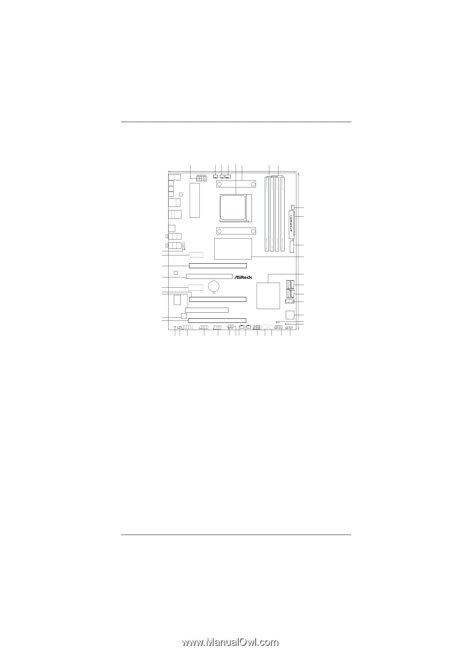
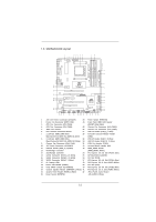
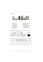
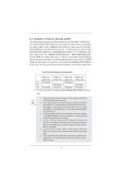
1.3 Motherboard Layout 1 234 24.4cm (9.6-in) 56 ATX12V1 PWR_FAN1 CPU_FAN2 CPU_FAN1 78 PS2 Mouse PS2 Coaxial Keyboard SPDIF 30.5cm (12.0-in) DDR3_B1 (64 bit, 240-FpinSBmo8d0ul0e) DDR3_B2 (64 bit, 240-pin module) DDR3_A2 (64 bit, 240-pin module) DDR3_A1 (64 bit, 240-FpinSBmo8d0ul0e) ErP/EuP Ready Support 8-Core CPU DDR3 2000+ AM3+ 140W CPU Optical SPDIF Clr CMOS IEEE 1394 eSATA3 LAN PHY USB 2.0 T: USB0 B: USB1 USB 2.0 T: USB2 B: USB3 USB 3.0 T: USB4 B: USB5 RJ-45 LAN SOCKET AM3b CHA_FAN1 9 10 RoHS 1 USB 3.0 Top: SIDE SPK Center: REAR SPK Bottom: CTR BASS 42 41 40 39 38 37 36 35 34 Designed in Taipei Top: LINE IN Center: FRONT Bottom: MIC IN USB_12_13 HD_AUDIO1 PCIE1 AMD 970 Chipset PCIE2 AUDIO CODEC PCI1 PCIE3 CMOS BATTERY Super I/O 32Mb BIOS HDMI_SPDIF1 IR1 1 1 COM1 PCIE4 PCI2 PCIE5 USB_10_11 USB_8_9 1 1 970 Extreme4 SATA3 6Gb/s SATA3_4_5 USB_6_7 1 1 CIR1 SATA3_2_3 AMD SB950 Chipset SATA3_1 X FAST USB CHA_FAN3 Front USB 3.0 1394a PLED1 FRONT_1394 1 PANEL 1 PLED PWRBTN 1 CHA_FAN2 PWRBTN1 RSTBTN1 1 HDLED RESET Dr. Debug CLRCMOS1 1 SPEAKER1 1 33 32 31 30 29 28 27 26 25 24 23 22 21 20 11 12 13 14 15 16 17 18 19 1 ATX 12V Power Connector (ATX12V1) 23 Power Switch (PWRBTN) 2 Power Fan Connector (PWR_FAN1) 24 Front Panel IEEE 1394 Header 3 CPU Fan Connector (CPU_FAN2) (FRONT_1394, White) 4 CPU Fan Connector (CPU_FAN1) 25 Chassis Fan Connector (CHA_FAN2) 5 AM3+ CPU Socket 26 Chassis Fan Connector (CHA_FAN3) 6 CPU Heatsink Retention Module 27 USB 2.0 Header (USB_6_7, Blue) 7 2 x 240-pin DDR3 DIMM Slots 28 Consumer Infrared Module Header (Dual Channel A: DDR3_A1, DDR3_B1; Blue) (CIR1) 8 2 x 240-pin DDR3 DIMM Slots 29 USB 2.0 Header (USB_8_9, Blue) (Dual Channel B: DDR3_A2, DDR3_B2; White) 30 USB 2.0 Header (USB_10_11, Blue) 9 Chassis Fan Connector (CHA_FAN1) 31 COM Port Header (COM1) 10 ATX Power Connector (ATXPWR1) 32 Infrared Module Header (IR1) 11 USB 3.0 Header (USB_12_13, Blue) 33 HDMI_SPDIF Header 12 Northbridge Controller (HDMI_SPDIF1, White) 13 Southbridge Controller 34 PCI Express 2.0 x16 Slot (PCIE5; Blue) 14 SATA3 Connector (SATA3_4_5, White) 35 SPI Flash Memory (32Mb) 15 SATA3 Connector (SATA3_2_3, White) 36 PCI Slot (PCI2) 16 SATA3 Connector (SATA3_1, White) 37 PCI Express 2.0 x16 Slot (PCIE4; Blue) 17 Dr. Debug (LED) 38 PCI Express 2.0 x1 Slot (PCIE3; White) 18 Power LED Header (PLED1) 39 PCI Slot (PCI1) 19 Clear CMOS Jumper (CLRCMOS1) 40 PCI Express 2.0 x16 Slot (PCIE2; Blue) 20 Chassis Speaker Header (SPEAKER 1, White) 41 PCI Express 2.0 x1 Slot (PCIE1; White) 21 System Panel Header (PANEL1, White) 42 Front Panel Audio Header 22 Reset Switch (RSTBTN) (HD_AUDIO1, White) 12
-
 1
1 -
2
-
3
-
4
-
5
-
6
-
 7
7 -
 8
8 -
 9
9 -
 10
10 -
 11
11 -
 12
12 -
 13
13 -
 14
14 -
 15
15 -
 16
16 -
 17
17 -
18
-
19
-
20
-
21
-
22
-
23
-
24
-
25
-
26
-
27
-
28
-
29
-
30
-
31
-
32
-
33
-
34
-
35
-
36
-
37
-
38
-
39
-
40
-
41
-
42
-
43
-
44
-
45
-
46
-
47
-
48
-
49
-
50
-
51
-
52
-
53
-
54
-
55
-
56
-
57
-
58
-
59
-
60
-
61
-
62
-
63
-
64
-
65
-
66
-
67
-
68
 |
 |