ASRock ALiveNF5-eSATA2 User Manual - Page 19
motherboard. Each USB 2.0
 |
View all ASRock ALiveNF5-eSATA2 manuals
Add to My Manuals
Save this manual to your list of manuals |
Page 19 highlights
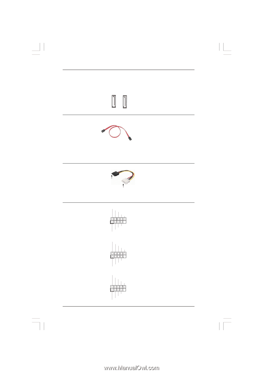
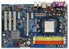
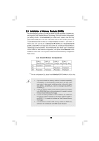
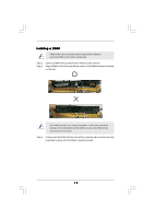
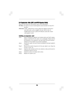
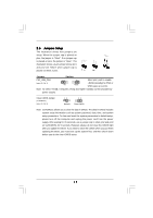
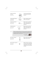
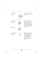
eSATA II Connectors (eSATAII_TOP: see p.10, No. 36) (eSATAII_BOTTOM: see p.10, No. 37) eSATAII_TOP eSATAII_BOTTOM These two eSATAII connectors support SATA data cables for external SATAII function. The current eSATA II interface allows up to 3.0 Gb/s data transfer rate. Serial ATA (SATA) Data Cable (Optional) Either end of the SATA data cable can be connected to the SATA / SATAII hard disk or the SATAII connector on the motherboard. You can also use the SATA data cable to connect SATAII connectors and eSATAII connectors with corresponding color. Serial ATA (SATA) Power Cable (Optional) connect to the SATA HDD power connector connect to the power supply Please connect the black end of SATA power cable to the power connector on each drive. Then connect the white end of SATA power cable to the power connector of the power supply. USB 2.0 Headers (9-pin USB8_9) (see p.10 No. 14) (9-pin USB6_7) (see p.10 No. 15) (9-pin USB4_5) (see p.10 No. 16) USB_PWR P-9 P+9 GND DUMMY 1 GND P+8 P-8 USB_PWR USB_PWR P-7 P+7 GND DUMMY 1 GND P+6 P-6 USB_PWR USB_PWR P-5 P+5 GND DUMMY 1 GND P+4 P-4 USB_PWR 19 Besides two default USB 2.0 ports on the I/O panel, there are four USB 2.0 headers on this motherboard. Each USB 2.0 header can support two USB 2.0 ports.
-
 1
1 -
2
-
3
-
4
-
5
-
6
-
7
-
8
-
9
-
10
-
11
-
12
-
13
-
 14
14 -
 15
15 -
 16
16 -
 17
17 -
 18
18 -
 19
19 -
 20
20 -
 21
21 -
 22
22 -
 23
23 -
 24
24 -
25
-
26
-
27
-
28
-
29
-
30
-
31
-
32
-
33
-
34
-
35
-
36
-
37
-
38
-
39
-
40
-
41
-
42
-
43
-
44
-
45
-
46
-
47
-
48
-
49
-
50
-
51
-
52
-
53
-
54
 |
 |