ASRock ALiveNF5-eSATA2 User Manual - Page 22
con nect HDMI Digital TV
 |
View all ASRock ALiveNF5-eSATA2 manuals
Add to My Manuals
Save this manual to your list of manuals |
Page 22 highlights
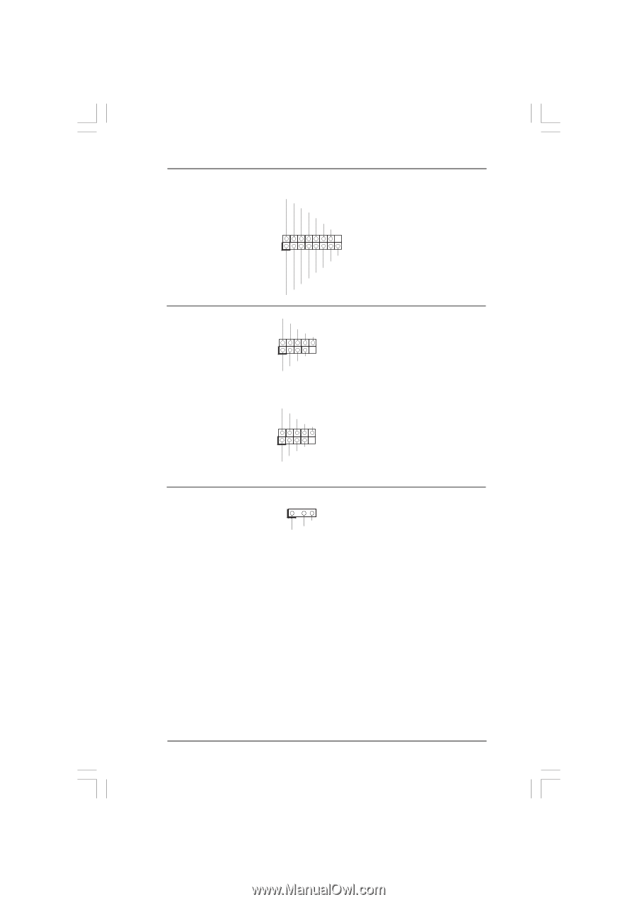
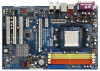
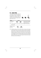
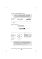
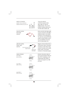
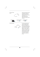
Game Port Header (15-pin GAME1) (see p.10, No. 24) IEEE 1394 Headers (9-pin FRONT_1394) (see p.10, No. 30) (9-pin BACK_1394) (see p.10, No. 29) HDMI_SPDIF Header (3-pin HDMI_SPDIF1) (see p.10, No. 27) +5V JBB1 JBX MIDI_OUT JBY JBB2 MIDI_IN 1 +5V JAB2 JAY GND GND JAX JAB1 +5V Connect a Game cable to this header if the Game port bracket is installed. RXTPAM_0 GND RXTPBM_0 +12V GND 1 +12V RXTPBP_0 GND RXTPAP_0 RXTPAM_0 GND RXTPBM_0 +12V GND 1 +12V RXTPBP_0 GND RXTPAP_0 There are two IEEE 1394 headers on this motherboard, including one front panel IEEE 1394 header (FRONT_1394) and one back panel IEEE 1394 header (BACK_1394). Each IEEE 1394 header can support one IEEE 1394 port. 1 GND +5V SPDIFOUT HDMI_SPDIF header, providing SPDIF audio output to HDMI VGA card, allows the system to connect HDMI Digital TV/ projector/LCD devices. Please connect the HDMI_SPDIF connector of HDMI VGA card to this header. 22
-
 1
1 -
2
-
3
-
4
-
5
-
6
-
7
-
8
-
9
-
10
-
11
-
12
-
13
-
14
-
15
-
16
-
 17
17 -
 18
18 -
 19
19 -
 20
20 -
 21
21 -
 22
22 -
 23
23 -
 24
24 -
 25
25 -
 26
26 -
 27
27 -
28
-
29
-
30
-
31
-
32
-
33
-
34
-
35
-
36
-
37
-
38
-
39
-
40
-
41
-
42
-
43
-
44
-
45
-
46
-
47
-
48
-
49
-
50
-
51
-
52
-
53
-
54
 |
 |