ASRock ALiveSATA2-GLAN Quick Installation Guide - Page 20
Hot Plug and Hot Swap Functions for SA
 |
View all ASRock ALiveSATA2-GLAN manuals
Add to My Manuals
Save this manual to your list of manuals |
Page 20 highlights
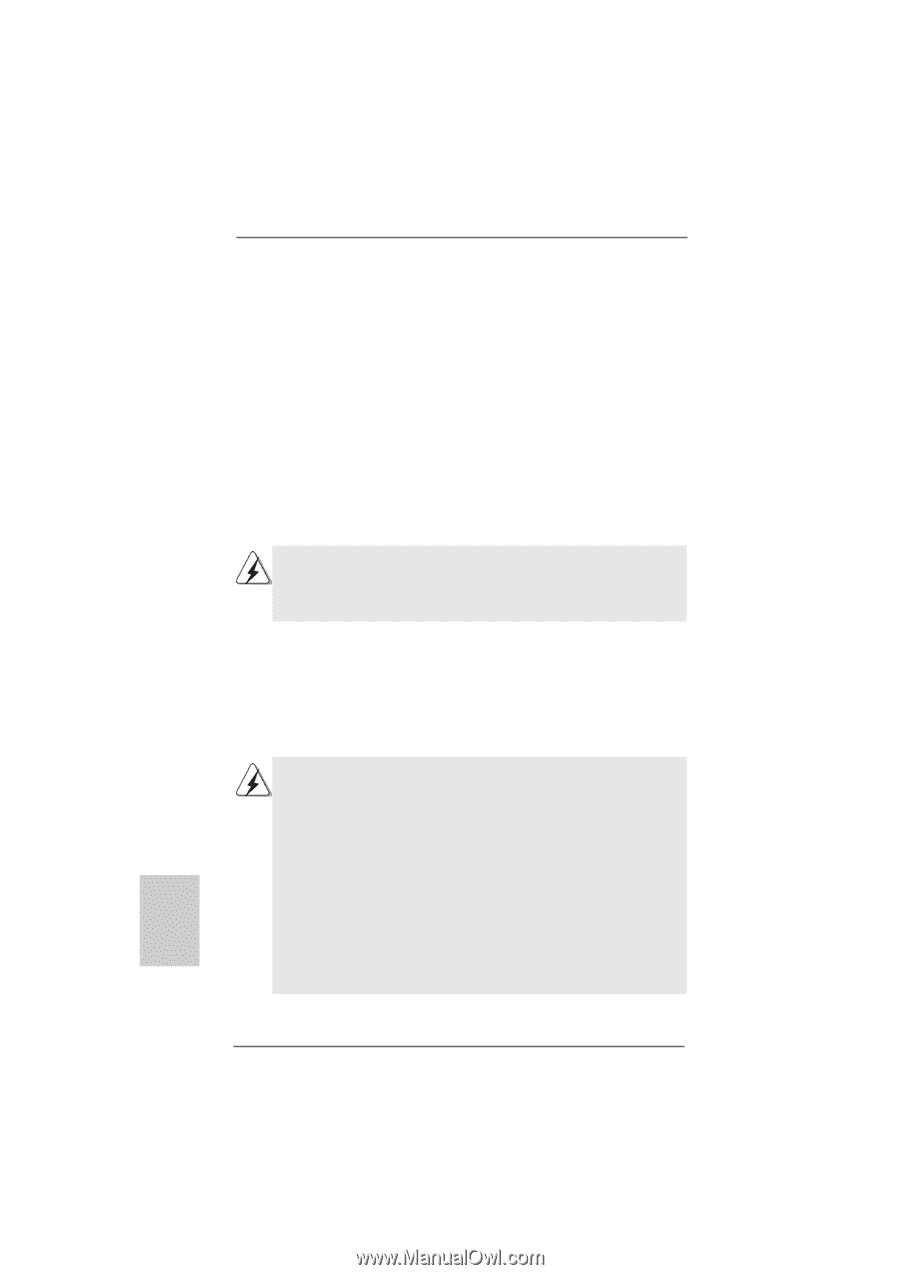
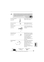
2.8 Serial ATA (SATA) / Serial ATAII (SATAII) Hard Disks Installation This motherboard adopts JMicron® JMB363 chipset that supports Serial ATAII (SATAII) hard disks. It also adopts VIA® VT8237A south bridge chipset that supports Serial ATA (SATA) hard disks, and supports RAID functions. You may install SATA / SATAII hard disks on this motherboard for internal storage devices. This section will guide you to install the SATA / SATAII hard disks. STEP 1: Install the SATA / SATAII hard disks into the drive bays of your chassis. STEP 2: Connect the SATA power cable to the SATA / SATAII hard disk. STEP 3: Connect one end of the SATA data cable to the motherboard's SATA / SATAII connector. STEP 4: Connect the other end of the SATA data cable to the SATA / SATAII hard disk. To create RAID with two HDDs, please insert the two HDDs simultaneously to either SATA connectors (black) or SATAII connectors (red). If you insert one HDD to SATA connector and the other HDD to SATAII connector, you are not allowed to create RAID. 2.9 Hot Plug and Hot Swap Functions for SATA / SATAII HDDs ALiveSATA2-GLAN motherboard supports Hot Plug and Hot Swap functions for SATA / SATAII Devices. NOTE What is Hot Plug Function? If the SATA / SATAII HDDs are NOT set for RAID configuration, it is called "Hot Plug" for the action to insert and remove the SATA / SATAII HDDs while the system is still power-on and in working condition. However, please note that it cannot perform Hot Plug if the OS has been installed into the SATA / SATAII HDD. What is Hot Swap Function? If SATA / SATAII HDDs are built as RAID1 then it is called "Hot Swap" for the action to insert and remove the SATA / SATAII HDDs while the system is still power-on and in working condition. 20 ASRock ALiveSATA2-GLAN Motherboard English
-
 1
1 -
2
-
3
-
4
-
5
-
6
-
7
-
8
-
9
-
10
-
11
-
12
-
13
-
14
-
 15
15 -
 16
16 -
 17
17 -
 18
18 -
 19
19 -
 20
20 -
 21
21 -
 22
22 -
 23
23 -
 24
24 -
 25
25 -
26
-
27
-
28
-
29
-
30
-
31
-
32
-
33
-
34
-
35
-
36
-
37
-
38
-
39
-
40
-
41
-
42
-
43
-
44
-
45
-
46
-
47
-
48
-
49
-
50
-
51
-
52
-
53
-
54
-
55
-
56
-
57
-
58
-
59
-
60
-
61
-
62
-
63
-
64
-
65
-
66
-
67
-
68
-
69
-
70
-
71
-
72
-
73
-
74
-
75
-
76
-
77
-
78
-
79
-
80
-
81
-
82
-
83
-
84
-
85
-
86
-
87
-
88
-
89
-
90
-
91
-
92
-
93
-
94
-
95
-
96
-
97
-
98
-
99
-
100
-
101
-
102
-
103
-
104
-
105
-
106
-
107
-
108
-
109
-
110
-
111
-
112
-
113
-
114
-
115
-
116
-
117
-
118
-
119
-
120
-
121
-
122
-
123
-
124
-
125
-
126
-
127
-
128
-
129
-
130
-
131
-
132
-
133
-
134
-
135
-
136
-
137
-
138
-
139
-
140
-
141
-
142
-
143
-
144
-
145
-
146
-
147
-
148
-
149
-
150
-
151
-
152
-
153
-
154
-
155
-
156
-
157
-
158
-
159
-
160
 |
 |