ASRock B450M-HDV R4.0 User Manual - Page 25
pin FAN cable, USB 2.0 Header
 |
View all ASRock B450M-HDV R4.0 manuals
Add to My Manuals
Save this manual to your list of manuals |
Page 25 highlights
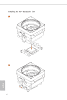
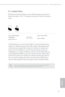
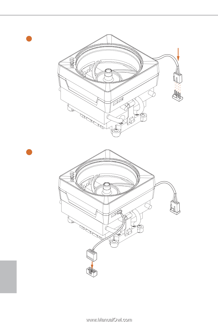
5 4-pin FAN cable CPU_FAN1 6 CPU_FAN1 USB 2.0 Header USB Please note that this connector is the interface to the LED control board on the SR3, it requires the AMD utility "SR3 Settings Software" to control the LED. *The diagram shown here are for reference only. Please refer to page 27 for the orientation of USB Header. 20 English
-
 1
1 -
2
-
3
-
4
-
5
-
6
-
7
-
8
-
9
-
10
-
11
-
12
-
13
-
14
-
15
-
16
-
17
-
18
-
19
-
 20
20 -
 21
21 -
 22
22 -
 23
23 -
 24
24 -
 25
25 -
 26
26 -
 27
27 -
 28
28 -
 29
29 -
 30
30 -
31
-
32
-
33
-
34
-
35
-
36
-
37
-
38
-
39
-
40
-
41
-
42
-
43
-
44
-
45
-
46
-
47
-
48
-
49
-
50
-
51
-
52
-
53
-
54
-
55
-
56
-
57
-
58
-
59
-
60
-
61
-
62
-
63
-
64
-
65
-
66
-
67
-
68
-
69
-
70
-
71
-
72
-
73
-
74
-
75
-
76
-
77
-
78
-
79
-
80
 |
 |
English
20
5
CPU_FAN1
Please note that this connector is the interface to the LED control board on the SR3, it requires the AMD
utility "SR3 Settings Soſtware" to control the LED.
*°e diagram shown here are for reference only. Please refer to page 27 for the orientation of USB Header.
CPU_FAN1
6
USB
4-pin FAN cable
USB 2.0 Header