ASRock B450M-HDV R4.0 User Manual - Page 32
Front Panel Audio Header, pin HD_AUDIO1
 |
View all ASRock B450M-HDV R4.0 manuals
Add to My Manuals
Save this manual to your list of manuals |
Page 32 highlights
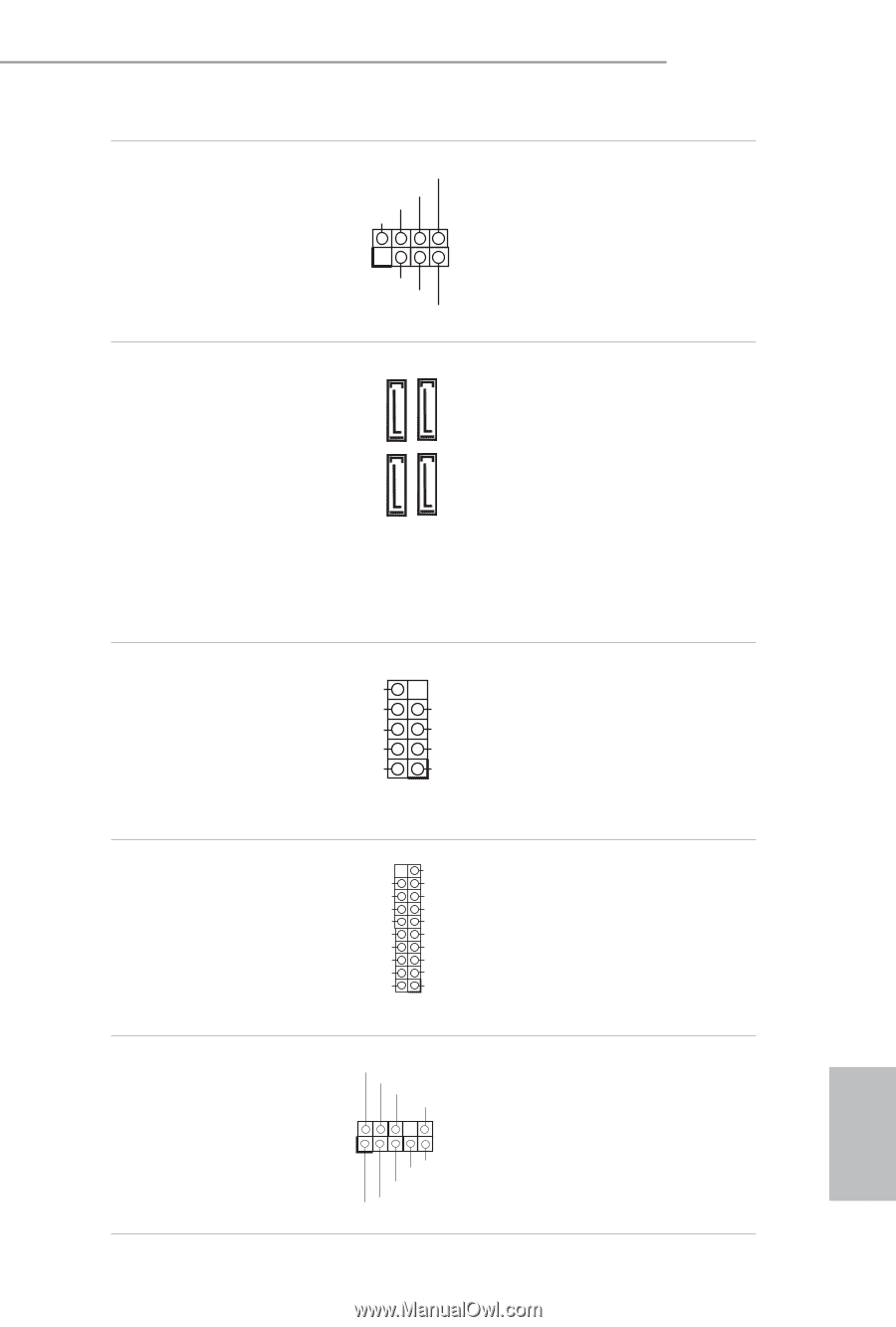
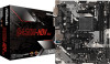
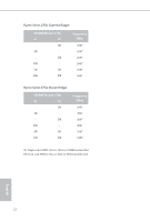
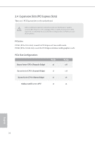
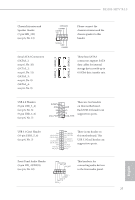
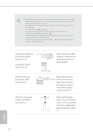
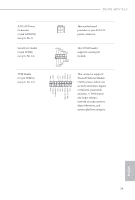
B450M-HDV R4.0 Chassis Intrusion and Speaker Header (7-pin SPK_CI1) (see p.6, No. 13) Serial ATA3 Connectors (SATA3_1: see p.6, No. 10) (SATA3_2: see p.6, No. 11) (SATA3_3: see p.6, No. 8) (SATA3_4: see p.6, No. 9) SATA3_1 SATA3_3 SATA3_2 SATA3_4 SPEAKER DUMMY DUMMY +5V 1 SIGNAL GND DUMMY Please connect the chassis intrusion and the chassis speaker to this header. These four SATA3 connectors support SATA data cables for internal storage devices with up to 6.0 Gb/s data transfer rate. USB 2.0 Headers (9-pin USB_3_4) (see p.6, No. 6) (9-pin USB_5_6) (see p.6, No. 7) DUMMY GND +B -B USB_PWR GND +A -A USB_PWR 1 There are two headers on this motherboard. Each USB 2.0 header can support two ports. USB 3.1 Gen1 Header (19-pin USB3_5_6) (see p.6, No. 5) Vbus IntA_PA_SSRXIntA_PA_SSRX+ GND IntA_PA_SSTXIntA_PA_SSTX+ GND IntA_PA_DIntA_PA_D+ Vbus IntA_PB_SSRXIntA_PB_SSRX+ GND IntA_PB_SSTXIntA_PB_SSTX+ GND IntA_PB_DIntA_PB_D+ Dummy 1 There is one header on this motherboard. This USB 3.1 Gen1 header can support two ports. Front Panel Audio Header (9-pin HD_AUDIO1) (see p.6, No. 18) GND PRESENCE# MIC_RET OUT_RET 1 OUT2_L J_SENSE OUT2_R MIC2_R MIC2_L This header is for connecting audio devices to the front audio panel. 27 English
-
 1
1 -
2
-
3
-
4
-
5
-
6
-
7
-
8
-
9
-
10
-
11
-
12
-
13
-
14
-
15
-
16
-
17
-
18
-
19
-
20
-
21
-
22
-
23
-
24
-
25
-
26
-
 27
27 -
 28
28 -
 29
29 -
 30
30 -
 31
31 -
 32
32 -
 33
33 -
 34
34 -
 35
35 -
 36
36 -
 37
37 -
38
-
39
-
40
-
41
-
42
-
43
-
44
-
45
-
46
-
47
-
48
-
49
-
50
-
51
-
52
-
53
-
54
-
55
-
56
-
57
-
58
-
59
-
60
-
61
-
62
-
63
-
64
-
65
-
66
-
67
-
68
-
69
-
70
-
71
-
72
-
73
-
74
-
75
-
76
-
77
-
78
-
79
-
80
 |
 |