ASRock B75M-DGS R2.0 User Guide - Page 15
BIOS Information, Software Support CD information
 |
View all ASRock B75M-DGS R2.0 manuals
Add to My Manuals
Save this manual to your list of manuals |
Page 15 highlights
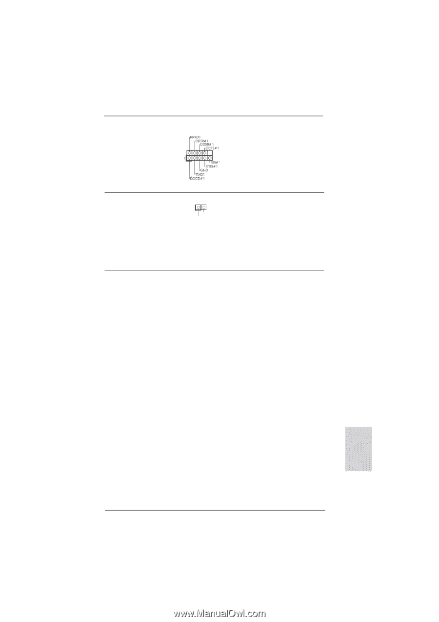
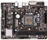
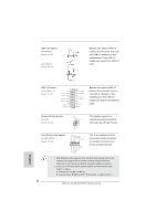
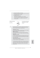
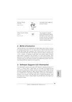
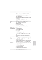
Serial port Header (9-pin COM1) (see p.2, No. 20) This COM1 header supports a serial port module. Chassis Intrusion Header (2-pin CI1) (see p.2, No. 25) 1 GND Signal This motherboard supports CASE OPEN detection feature that detects if the chassis cover has been removed. This feature requires a chassis with chassis intrusion detection design. 2. BIOS Information The Flash Memory on the motherboard stores BIOS Setup Utility. When you start up the computer, please press or during the Power-On-Self-Test (POST) to enter BIOS Setup utility; otherwise, POST continues with its test routines. If you wish to enter BIOS Setup after POST, please restart the system by pressing + + , or pressing the reset button on the system chassis. The BIOS Setup program is designed to be user-friendly. It is a menu-driven program, which allows you to scroll through its various sub-menus and to select among the predetermined choices. For the detailed information about BIOS Setup, please refer to the User Manual (PDF file) contained in the Support CD. 3. Software Support CD information This motherboard supports various Microsoft® Windows® operating systems: 8 / 8 64-bit / 7 / 7 64-bit / VistaTM / VistaTM 64-bit / XP / XP 64-bit. The Support CD that came with the motherboard contains necessary drivers and useful utilities that will enhance motherboard features. To begin using the Support CD, insert the CD into your CD-ROM drive. It will display the Main Menu automatically if "AUTORUN" is enabled in your computer. If the Main Menu does not appear automatically, locate and double-click on the file "ASSETUP.EXE" from the BIN folder in the Support CD to display the menus. 15 ASRock B75M-DGS R2.0 Motherboard English
-
 1
1 -
2
-
3
-
4
-
5
-
6
-
7
-
8
-
9
-
 10
10 -
 11
11 -
 12
12 -
 13
13 -
 14
14 -
 15
15 -
 16
16 -
 17
17 -
 18
18 -
 19
19 -
 20
20 -
21
-
22
-
23
-
24
-
25
-
26
-
27
-
28
-
29
-
30
-
31
-
32
-
33
-
34
-
35
-
36
-
37
-
38
-
39
-
40
-
41
-
42
-
43
-
44
-
45
-
46
-
47
-
48
-
49
-
50
-
51
-
52
 |
 |