ASRock B75M-DGS R2.0 User Guide - Page 9
English, Pin Header Easy Installation Guide
 |
View all ASRock B75M-DGS R2.0 manuals
Add to My Manuals
Save this manual to your list of manuals |
Page 9 highlights
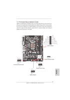
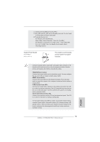
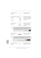
1.3 Pin Header Easy Installation Guide ASRock motherboard is equipped with pin headers with obvious colors which indicate you to recognize the crucial headers more easily. Please refer to below illustrations for the pin definition of onboard headers. If you want to have more information about the usage of these headers, please refer to "Jumpers Setup" and "Onboard Headers and Connectors" for details. IntA_P_D+ IntA_P_DGND IntA_P_SSTX+ IntA_P_SSTXGND IntA_P_SSRX+ IntA_P_SSRXVbus 1 Vbus IntA_P_SSRXIntA_P_SSRX+ GND IntA_P_SSTXIntA_P_SSTX+ GND IntA_P_DIntA_P_D+ ID USB 3.0 Header GND PRESENCE# MIC_RET OUT_RET 1 OUT2_L J_SENSE OUT2_R MIC2_R MIC2_L Front Panel Audio Header 1 SPEAKER DUMMY +5V DUMMY Chassis Speaker Header PLED+ PLED- PWRBTN# GND USB_PWR PP+GND DUMMY 1 DUMMY REST# GND HDLEDHDLED+ System Panel Header 1 GND P+ PUSB_PWR USB 2.0 Header 9 ASRock B75M-DGS R2.0 Motherboard English
-
 1
1 -
2
-
3
-
 4
4 -
 5
5 -
 6
6 -
 7
7 -
 8
8 -
 9
9 -
 10
10 -
 11
11 -
 12
12 -
 13
13 -
 14
14 -
15
-
16
-
17
-
18
-
19
-
20
-
21
-
22
-
23
-
24
-
25
-
26
-
27
-
28
-
29
-
30
-
31
-
32
-
33
-
34
-
35
-
36
-
37
-
38
-
39
-
40
-
41
-
42
-
43
-
44
-
45
-
46
-
47
-
48
-
49
-
50
-
51
-
52
 |
 |
