ASRock C621A WS Quick Installation Guide - Page 30
Mini-SAS HD Connector
 |
View all ASRock C621A WS manuals
Add to My Manuals
Save this manual to your list of manuals |
Page 30 highlights
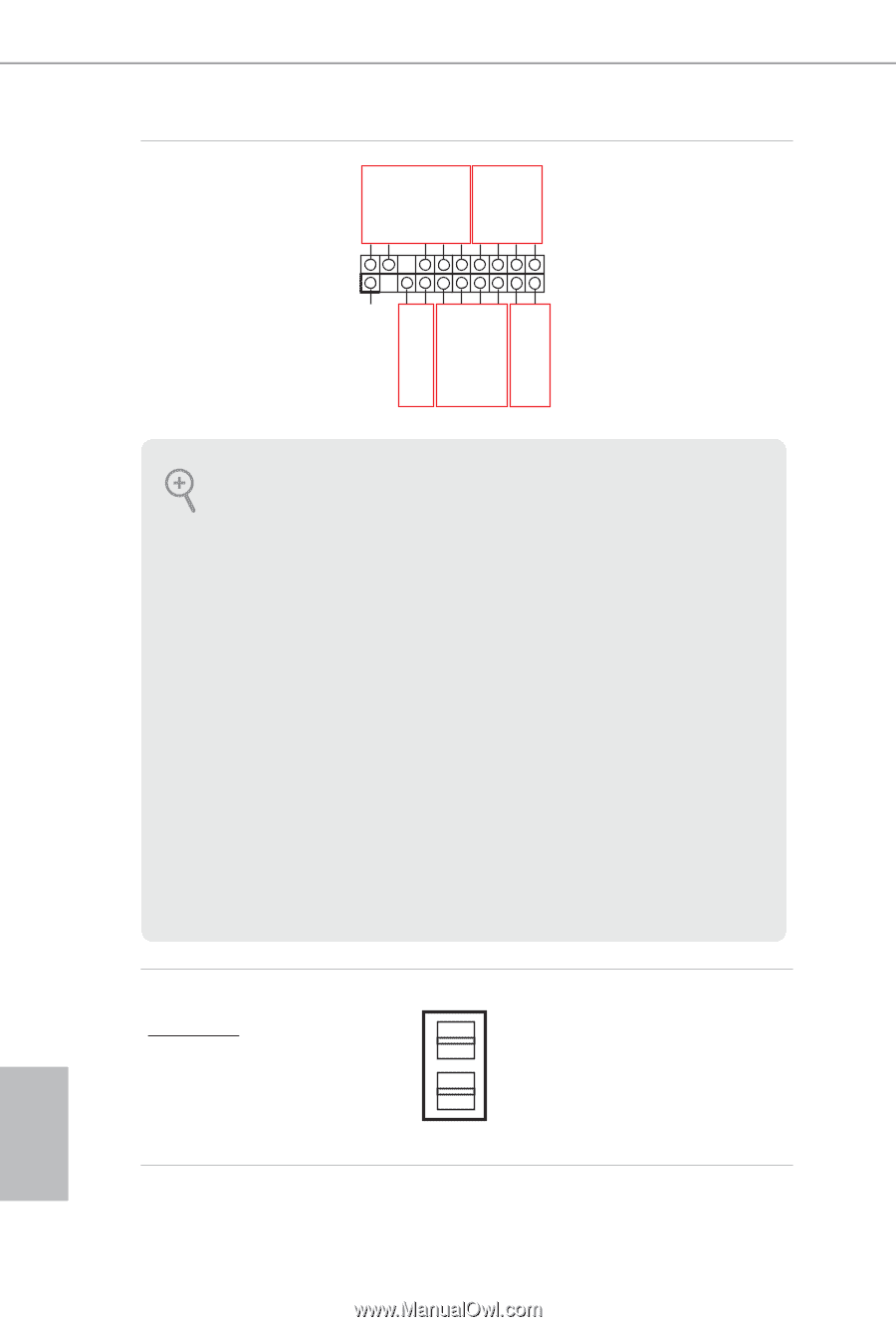
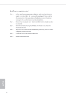
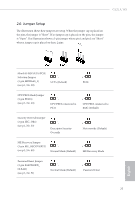
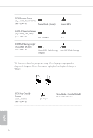
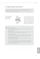
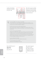
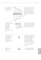
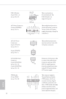
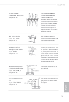
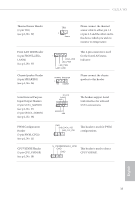
Auxiliary Panel Header A (18-pin AUX_PANEL1) (see p.1, No. 30) 1 SMB_Alert SMB_CLK GND SMB_DATA +3VSB LAN1_LINK LED_PWR LED_PWR LAN2_LINK B This header supports multiple functions on the front panel, including the front panel SMB, internet status indicator and chassis intrusion pin. +5VSB CASEOPEN GND LOCATORLED1+ LOCATORLED1- LOCATORBTN# GND System Fault LEDSystem Fault LED+ C D E A. Front panel SMBus connecting pin (6-1 pin FPSMB) This header allows you to connect SMBus (System Management Bus) equipment. It can be used for communication between peripheral equipment in the system, which has slower transmission rates, and power management equipment. B. Internet status indicator (2-pin LAN1_LED, LAN2_LED) These two 2-pin headers allow you to use the Gigabit internet indicator cable to connect to the LAN status indicator. When this indicator flickers, it means that the internet is properly connected. C. Chassis intrusion pin (2-pin CHASSIS) This header is provided for host computer chassis with chassis intrusion detection designs. In addition, it must also work with external detection equipment, such as a chassis intrusion detection sensor or a microswitch. When this function is activated, if any chassis component movement occurs, the sensor will immediately detect it and send a signal to this header, and the system will then record this chassis intrusion event. The default setting is set to the CASEOPEN and GND pin; this function is off. D. Locator LED (4-pin LOCATOR) This header is for the locator switch and LED on the front panel. E. System Fault LED (2-pin LOCATOR) This header is for the Fault LED on the system. Mini-SAS HD Connector Right-Angle: (SATA_0_3) (see p.1, No. 22) This connector supports MiniSAS-to-SATA data cables for internal storage devices with up to 6.0 Gb/s data transfer SATA_0_3 rate. English 28
-
 1
1 -
2
-
3
-
4
-
5
-
6
-
7
-
8
-
9
-
10
-
11
-
12
-
13
-
14
-
15
-
16
-
17
-
18
-
19
-
20
-
21
-
22
-
23
-
24
-
 25
25 -
 26
26 -
 27
27 -
 28
28 -
 29
29 -
 30
30 -
 31
31 -
 32
32 -
 33
33 -
 34
34 -
 35
35 -
36
-
37
-
38
-
39
-
40
-
41
-
42
-
43
-
44
-
45
-
46
-
47
-
48
-
49
-
50
-
51
-
52
-
53
-
54
-
55
-
56
-
57
-
58
-
59
-
60
-
61
-
62
-
63
-
64
-
65
-
66
-
67
-
68
-
69
-
70
-
71
-
72
-
73
-
74
-
75
-
76
-
77
-
78
-
79
-
80
-
81
-
82
-
83
-
84
-
85
-
86
-
87
-
88
-
89
-
90
-
91
-
92
-
93
-
94
-
95
-
96
-
97
-
98
-
99
-
100
-
101
-
102
-
103
-
104
-
105
-
106
-
107
-
108
-
109
-
110
-
111
-
112
-
113
-
114
-
115
-
116
-
117
-
118
-
119
-
120
-
121
-
122
-
123
-
124
-
125
-
126
-
127
-
128
-
129
-
130
-
131
-
132
-
133
-
134
-
135
-
136
-
137
-
138
-
139
-
140
-
141
-
142
-
143
-
144
-
145
-
146
-
147
-
148
-
149
-
150
-
151
-
152
-
153
-
154
-
155
-
156
-
157
-
158
-
159
-
160
-
161
-
162
-
163
-
164
-
165
-
166
-
167
-
168
-
169
-
170
-
171
-
172
-
173
-
174
-
175
-
176
-
177
-
178
-
179
-
180
-
181
-
182
-
183
-
184
-
185
-
186
-
187
-
188
-
189
-
190
-
191
-
192
-
193
-
194
-
195
-
196
-
197
-
198
-
199
-
200
-
201
-
202
-
203
-
204
-
205
-
206
-
207
-
208
-
209
-
210
-
211
-
212
-
213
-
214
-
215
-
216
-
217
-
218
-
219
-
220
-
221
-
222
-
223
 |
 |