ASRock C621A WS Quick Installation Guide - Page 32
ATX 12V Power
 |
View all ASRock C621A WS manuals
Add to My Manuals
Save this manual to your list of manuals |
Page 32 highlights
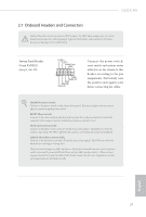
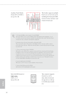
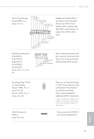
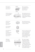
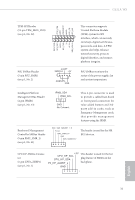
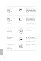
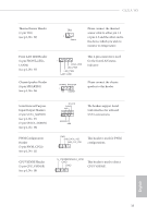
USB 2.0 Header (9-pin USB_2_3) (see p.1, No. 27) ATX Power Connector (24-pin ATXPWR1) (see p.1, No. 4) USB_PWR PP+ GND DUMMY 1 GND P+ PUSB_PWR This is one header on this motherboard. This USB 2.0 header can support two ports. 3V 12V 12V 5VSB PWROK_PS GND 5V GND 5V GND 3V 3V This motherboard provides a 24-pin ATX power connector. 1 12 To use a 20-pin ATX power 13 24 supply, please plug it along Pin 1 and Pin 13. GND 5V 5V 5V N/A GND GND GND PSON# GND -12V 3V ATX 12V Power Connectors (8-pin ATX12V1) (see p.1, No. 5) (4-pin ATX12V2) (see p.1, No. 7) SATA DOM Power Connector (3-pin SATAPWR1) (see p.1, No. 15) (3-pin SATAPWR2) (see p.1, No. 12) TPM Header (17-pin TPM1) (see p.1, No. 36) 30 GND SERIRQ# S_PWRDWN# GND LAD1 LAD2 SMB_DATA_MAIN SMB_CLK_MAIN GND GND +3VSB LAD0 +3V LAD3 PCIRST# LFRAME# PCICLK GND 1 4 5 8 12V GND 1 2 3 4 12V +5V GND +12V This motherboard provides one 8-pin and one 4-pin ATX 12V power connectors. Please use a SATA power cable to connect this SATA Power Connector and your SATA HDD for supplying power from the motherboard, when using DC-IN mode without SATA power supply. This connector supports Trusted Platform Module (TPM) system, which can 1 securely store keys, digital certificates, passwords, and data. A TPM system also helps enhance network security, protects digital identities, and ensures platform integrity. English
-
 1
1 -
2
-
3
-
4
-
5
-
6
-
7
-
8
-
9
-
10
-
11
-
12
-
13
-
14
-
15
-
16
-
17
-
18
-
19
-
20
-
21
-
22
-
23
-
24
-
25
-
26
-
 27
27 -
 28
28 -
 29
29 -
 30
30 -
 31
31 -
 32
32 -
 33
33 -
 34
34 -
 35
35 -
 36
36 -
 37
37 -
38
-
39
-
40
-
41
-
42
-
43
-
44
-
45
-
46
-
47
-
48
-
49
-
50
-
51
-
52
-
53
-
54
-
55
-
56
-
57
-
58
-
59
-
60
-
61
-
62
-
63
-
64
-
65
-
66
-
67
-
68
-
69
-
70
-
71
-
72
-
73
-
74
-
75
-
76
-
77
-
78
-
79
-
80
-
81
-
82
-
83
-
84
-
85
-
86
-
87
-
88
-
89
-
90
-
91
-
92
-
93
-
94
-
95
-
96
-
97
-
98
-
99
-
100
-
101
-
102
-
103
-
104
-
105
-
106
-
107
-
108
-
109
-
110
-
111
-
112
-
113
-
114
-
115
-
116
-
117
-
118
-
119
-
120
-
121
-
122
-
123
-
124
-
125
-
126
-
127
-
128
-
129
-
130
-
131
-
132
-
133
-
134
-
135
-
136
-
137
-
138
-
139
-
140
-
141
-
142
-
143
-
144
-
145
-
146
-
147
-
148
-
149
-
150
-
151
-
152
-
153
-
154
-
155
-
156
-
157
-
158
-
159
-
160
-
161
-
162
-
163
-
164
-
165
-
166
-
167
-
168
-
169
-
170
-
171
-
172
-
173
-
174
-
175
-
176
-
177
-
178
-
179
-
180
-
181
-
182
-
183
-
184
-
185
-
186
-
187
-
188
-
189
-
190
-
191
-
192
-
193
-
194
-
195
-
196
-
197
-
198
-
199
-
200
-
201
-
202
-
203
-
204
-
205
-
206
-
207
-
208
-
209
-
210
-
211
-
212
-
213
-
214
-
215
-
216
-
217
-
218
-
219
-
220
-
221
-
222
-
223
 |
 |
