ASRock C621A WS Quick Installation Guide - Page 53
Erkennung von CPU1 VSENSE
 |
View all ASRock C621A WS manuals
Add to My Manuals
Save this manual to your list of manuals |
Page 53 highlights
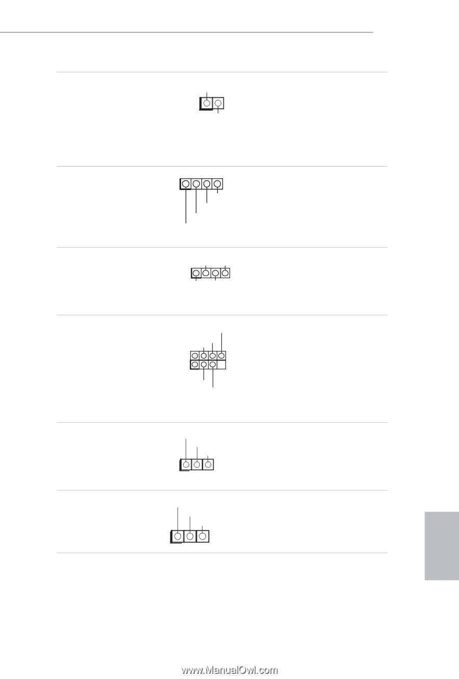
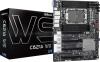
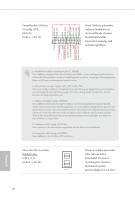
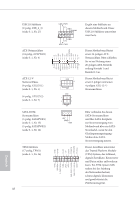
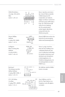
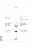
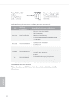
C621A WS WärmesensorSteckerleiste (2-polig, TR1) (siehe S. 1, Nr. 39) TR1 1 GND Bitte verbinden Sie das Thermosensor-Kabel mit Pin 1-2 oder Pin 2-3 und das andere Ende mit dem Gerät, das Sie zur Überwachung der Temperatur nutzen möchten. Front-LAN-LEDStiftleiste (4-polig, FRONT_LED_ LAN34) (siehe S. 1, Nr. 35) 1 LAN4_LINK LED_PWR LED_PWR LAN3_LINK Dieser 4-polige Anschluss wird für die Front-LANStatusanzeige verwendet. Gehäuselautsprecherstiftleiste (4-polig, SPEAKER1) (siehe S. 1, Nr. 26) DUMMY SPEAKER 1 +5V DUMMY Bitte verbinden Sie den Gehäuselautsprecher mit dieser Stiftleiste. Serielle-AllzweckEingang/AusgangStiftleisten (7-polig, SATA_SGPIO1) (siehe S. 1, Nr. 37) (7-polig, SSATA_SGPIO1) (siehe S. 1, Nr. 38) SCLOCK SLOAD GND 1 SDATAOUT GND Die Stiftleisten unterstützt serielle Verbindungsschnittstelle für Onboard-SATAVerbindungen. PWM-KonfigurationStiftleiste (3-polig, PWM_CFG1) (siehe S. 1, Nr. 11) GND SMB_DATA_VSB SMB_CLK_VSB 1 Diese Stiftleiste wird für PWM-Konfigurationen verwendet. CPU-VSENSE-Stiftleiste (3-polig, CPU_VSENSE) (siehe S. 1, Nr. 10) H_VSENSEINPMAX_CPU1 GND GND 1 Diese Stiftleiste wird zur Erkennung von CPU1 VSENSE verwendet. Deutsch 51
-
 1
1 -
2
-
3
-
4
-
5
-
6
-
7
-
8
-
9
-
10
-
11
-
12
-
13
-
14
-
15
-
16
-
17
-
18
-
19
-
20
-
21
-
22
-
23
-
24
-
25
-
26
-
27
-
28
-
29
-
30
-
31
-
32
-
33
-
34
-
35
-
36
-
37
-
38
-
39
-
40
-
41
-
42
-
43
-
44
-
45
-
46
-
47
-
 48
48 -
 49
49 -
 50
50 -
 51
51 -
 52
52 -
 53
53 -
 54
54 -
 55
55 -
 56
56 -
 57
57 -
 58
58 -
59
-
60
-
61
-
62
-
63
-
64
-
65
-
66
-
67
-
68
-
69
-
70
-
71
-
72
-
73
-
74
-
75
-
76
-
77
-
78
-
79
-
80
-
81
-
82
-
83
-
84
-
85
-
86
-
87
-
88
-
89
-
90
-
91
-
92
-
93
-
94
-
95
-
96
-
97
-
98
-
99
-
100
-
101
-
102
-
103
-
104
-
105
-
106
-
107
-
108
-
109
-
110
-
111
-
112
-
113
-
114
-
115
-
116
-
117
-
118
-
119
-
120
-
121
-
122
-
123
-
124
-
125
-
126
-
127
-
128
-
129
-
130
-
131
-
132
-
133
-
134
-
135
-
136
-
137
-
138
-
139
-
140
-
141
-
142
-
143
-
144
-
145
-
146
-
147
-
148
-
149
-
150
-
151
-
152
-
153
-
154
-
155
-
156
-
157
-
158
-
159
-
160
-
161
-
162
-
163
-
164
-
165
-
166
-
167
-
168
-
169
-
170
-
171
-
172
-
173
-
174
-
175
-
176
-
177
-
178
-
179
-
180
-
181
-
182
-
183
-
184
-
185
-
186
-
187
-
188
-
189
-
190
-
191
-
192
-
193
-
194
-
195
-
196
-
197
-
198
-
199
-
200
-
201
-
202
-
203
-
204
-
205
-
206
-
207
-
208
-
209
-
210
-
211
-
212
-
213
-
214
-
215
-
216
-
217
-
218
-
219
-
220
-
221
-
222
-
223
 |
 |